Receiver – Rainbow Electronics DS3150 User Manual
Page 5
DS3150
5 of 22
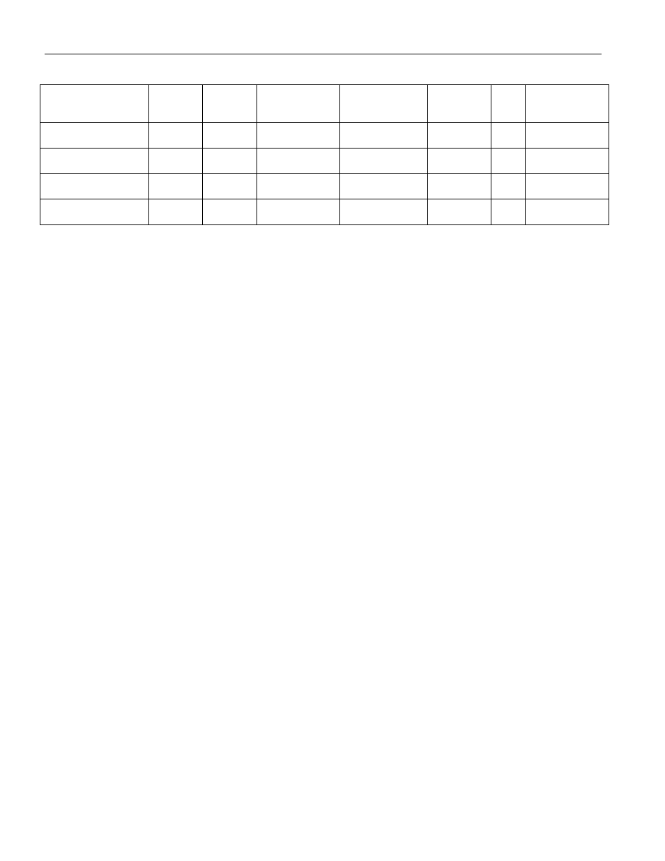
Table 1B. DS3150 T3/E3/STS-1 LIU TRANSFORMER RECOMMENDATIONS
MANUFACTURER
PART
NO.
TURNS
RATIO
PKG/
SCHEMATIC
DESCRIPTION
OCL
PRIMARY
µµµµ
H
L
L
µµµµ
H
BANDWIDTH
75
Ω
Ω
Ω
Ω
(MHz)
Pulse Engineering
PE-
65968
1:2CT
LS-1/C
6-pin SMT
19
0.06
0.250 to 500
Pulse Engineering
PE-
65969
1:2CT
LC-1/C
6-pin thru-hole
19
0.06
0.250 to 500
Halo Electronics
TG07-
0206NS
1:2CT
SMD/B
6-pin SMT
19
0.06
0.250 to 500
Halo Electronics
TD07-
0206NE
1:2CT
DIP/B
6-pin DIP
19
0.06
0.250 to 500
Note: Table subject to change. Commercial Temp: 0°C to +70
°
C
RECEIVER
The DS3150 interfaces to the receive T3/E3/STS-1 coax line through a 1:2 step-up transformer
(Figure 1B). The receiver automatically adapts to coax cable loses from 0dB to 15dB, which translates
into 0m to 380m (T3) or 440m (E3) or 360m (STS-1) of coax cable (AT&T 734A or equivalent). The
receiver also has the ability to interface to monitor jacks. Through the RMON input (Table 2A), the
device can be configured to insert a 20dB flat boost into the incoming signal. Monitor jacks typically
have series resistors that result in a resistive loss of 20dB. The receiver has excellent jitter tolerance
characteristics (Figure 1C).
The receiver contains both analog and digital loss-of-signal (LOS) detectors. The analog LOS detector
resides in the equalizer. If the incoming signal drops below -24dB of the nominal signal level, the analog
LOS detector will activate and it will step on the recovered data and force all zeros out of the data
recovery circuitry. The analog LOS detector will not clear until the signal level is above
-18dB of the nominal signal level. The digital LOS detector is activated when it detects 192
±
1
consecutive zeros. LOS is cleared when there are no excessive zero occurrences over a span of 192
±
1
clock periods. An excessive zero occurrence is defined as three or more consecutive zeros in the T3 and
STS-1 modes and four or more zeros in the E3 mode. The status of the digital LOS is reflected at the
LOS* output (Table 2A). There is no status output available for the analog LOS detector. While the
device is in a LOS state, the RCLK output will be referenced to the MCLK input (or the TCLK input if
MCLK is high/floating or to the internal oscillator if MCLK is tied low). The analog LOS detector has a
longer time constant than the digital LOS. Hence, when the incoming signal is lost, the digital LOS will
activate first followed by the analog LOS detector. When a signal is restored, the digital LOS will not be
allowed to qualify a signal for no excessive zero violations until the analog LOS detector has seen the
signal rise above -18dB. Governing specifications for the LOS detectors are ANSI T1.231 and ITU
G.775.
The recovered data from the receiver can be output in either bipolar format or nonreturn-to-zero (NRZ)
format. To select the bipolar format, the ZCSE* input is tied high. In this format, the B3ZS/HDB3
decoder is disabled and the received data is buffered and then output on the RPOS and RNEG outputs. To
select the NRZ format, the ZCSE* input is tied low. In this format, the B3ZS/HBD3 decoder is enabled
and the recovered data is B3ZS/HDB3 decoded and then logically OR’ed together at the RNRZ output,
while the RLCV output indicates line code violations.