Ac characteristics–digital (-40 ° c to +85 ° c; v, 3v ± 5%), Figure 3a. ac timing diagram – Rainbow Electronics DS3150 User Manual
Page 18
DS3150
18 of 22
AC CHARACTERISTICS–DIGITAL
(-40
°
C to +85
°
C; V
DD
= 3.3V
±
5%)
PARAMETER SYMBOL
MIN
TYP
MAX
UNITS
NOTES
RCLK/TCLK Clock Period
t1
t1
t1
22.4
29.1
19.3
ns
ns
ns
1
2
3
RCLK Clock High/Low Time
t2 / t3
t2 / t3
t2 / t3
9.0
11.6
7.7
11.2
14.5
9.6
13.4
17.4
11.5
ns
ns
ns
1
2
3
TCLK Clock High / Low Time
t2 / t3
7
ns
TPOS/TNRZ, TNEG to TCLK
Setup Time
t4 2 ns
TPOS/TNRZ, TNEG Hold Time
t5
2
ns
RCLK to RPOS/RNRZ Valid,
RNEG/RLCV Valid, Signal Change
on PRBS
t6 2 6 ns
4,
5
NOTES:
1) T3 Mode.
2) E3 Mode.
3) STS-1 Mode.
4) In Normal Mode, TPOS/TNRZ and TNEG are sampled on the rising edge of TCLK and RPOS/RNRZ
and RNEG/RLCV are updated on the falling edge of RCLK.
5) In Inverted Mode, TPOS/TNRZ and TNEG are sampled on the falling edge of TCLK and
RPOS/RNRZ and RNEG/RLCV are updated on the rising edge of RCLK.
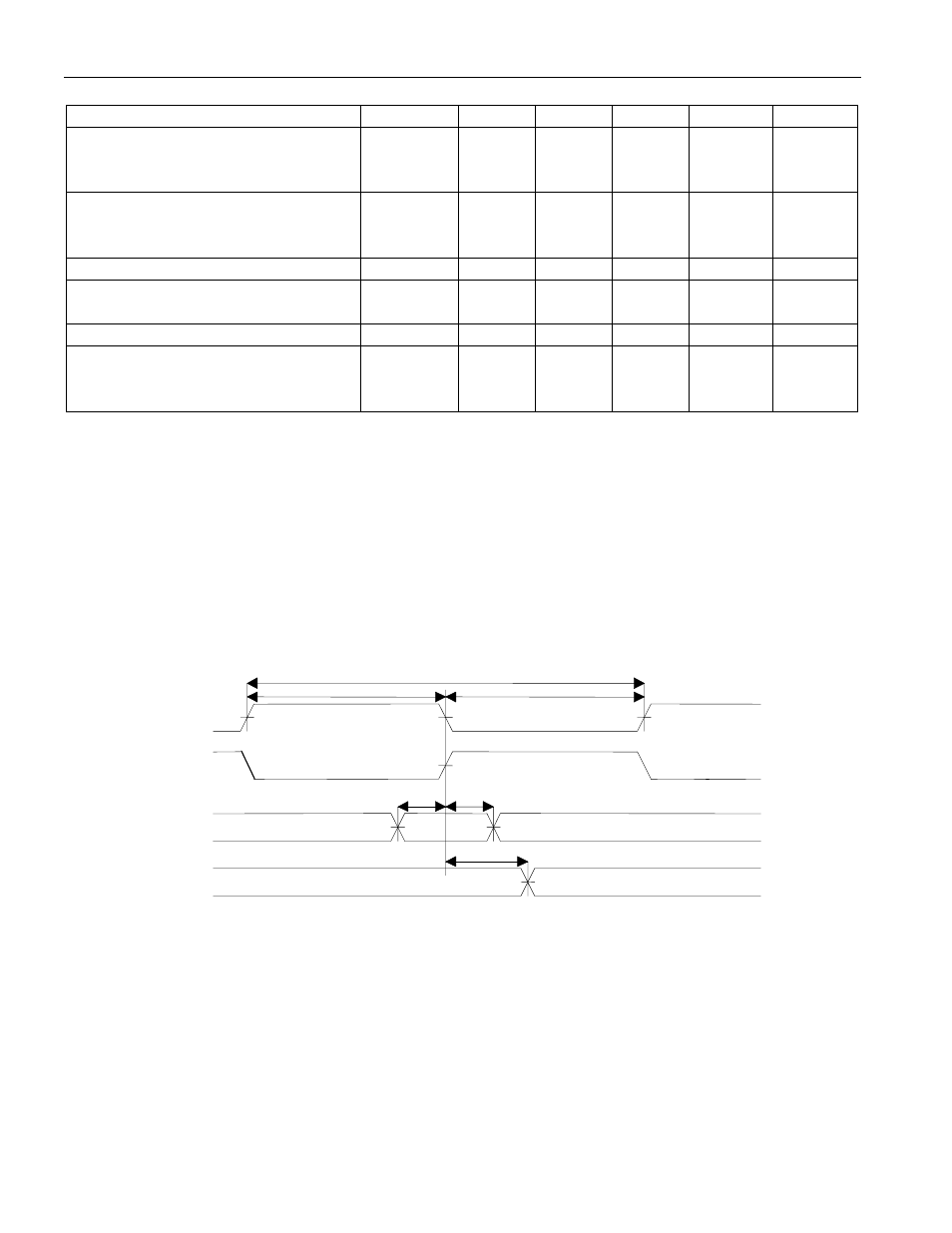
Figure 3A. AC TIMING DIAGRAM
RCLK (normal mode) /
TCLK (inverted mode)
TPOS/TNRZ, TNEG
RPOS/RNRZ,
RNEG/RLCV, PRBS
t4
t5
t6
t1
t2
t3
TCLK (normal mode) /
RCLK (inverted mode)
ac
_tim