Functional description, Ds3150, 3 of 22 – Rainbow Electronics DS3150 User Manual
Page 3
DS3150
3 of 22
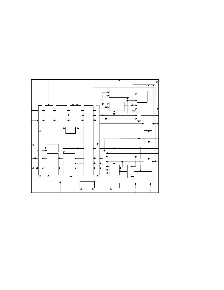
1. FUNCTIONAL DESCRIPTION
The DS3150 performs all the functions necessary for interfacing at the physical layer to T3, E3, and STS-
1 lines. The device has independent receive and transmit paths (Figure 1A). The receiver performs clock
and data recovery from a B3ZS-code or HDB3-code AMI signal and monitors for loss of the incoming
signal. The recovered data optionally can be B3ZS/HDB3 decoded and output in NRZ format. The
transmitter accepts either NRZ or bipolar data and drives standard pulse-shape waveforms onto 75Ω
coaxial cable. The receiver and transmitter sections will be discussed separately below. Table 1A lists the
telecommunications standards that the DS3150 was designed to meet.
Figure 1A. DS3150 BLOCK DIAGRAM
Analog
Loopback
20dB
Flat
Gain
Filter/
Equalizer
(Analog
Loss Of
Signal
Detect)
Clock &
Data
Recovery
Line
Driver
Wave-
Shaping
Clock
Invert
Clock
Invert
RX+
RX-
TX+
TX-
TTS*
PRBS
LBO
ZCSE*
ICE
TPOS/TNRZ
TCLK
TNEG
TESS
RNEG/RLCV
RCLK
RPOS/RNRZ
LOS*
MCLK
RMON
Remote
Loopback
liu_bd
EFE
V
DD
V
SS
Power
Connections
Test Functions
TDS0
TDS1
B3ZS/
HDB3
Encoder
AIS/
1010.../
PRBS
Generation
Mux
Mux
mux
PRBS
Detector
B3ZS/HDB3
Decoder
Digital Loss Of
Signal Detector
Squelch
Jitter A
ttenuat
o
r
(can be
pl
aced i
n
ei
ther t
h
e rec
e
iv
e path
or t
h
e transmi
t path
)
Driver
Monitor
Output Decode
Loopback Control
DM*
LBKS*