Write commands, At83c24 – Rainbow Electronics AT83C24NDS User Manual
Page 8
8
4234F–SCR–10/05
AT83C24
Write Commands
The write commands are:
1.
Reset:
Initializes all the logic and the TWI interface as after a power-up or power-fail reset. If a
smart card is active when RESET falls, a deactivation sequence is performed. This is a one-
byte command.
2.
Write Config:
Configures the device according to the last six bits in the CONFIG0 register and to the fol-
lowing four bytes in CONFIG1, CONFIG2, CONFIG3 then CONFIG4 registers. This is a
five bytes command.
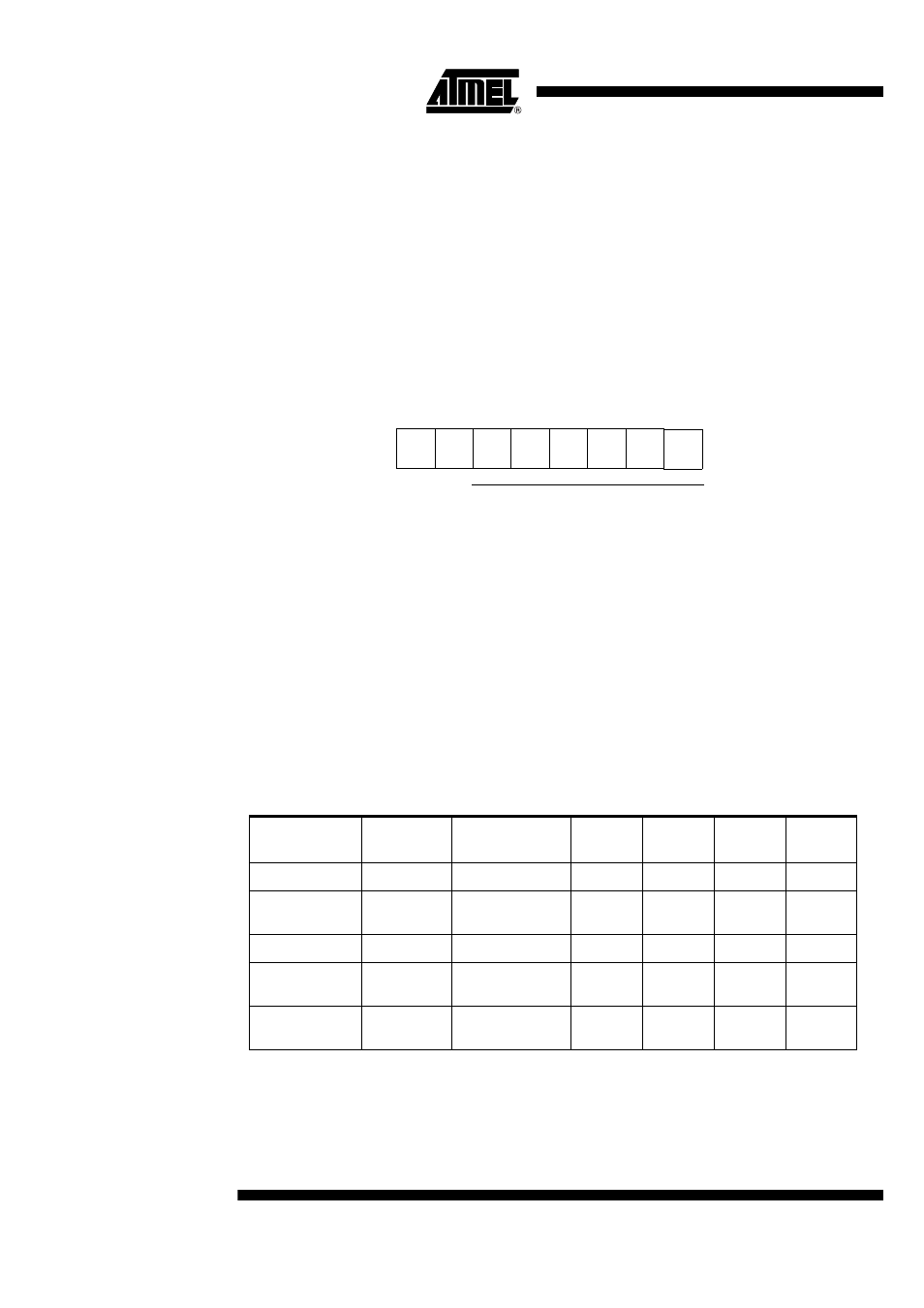
Figure 3. Command byte format for Write CONFIG0 command
3.
Write Timer:
Program the 16-bit automatic reset transition timer with the following two bytes. This is a
three bytes command.
4.
Write Interface:
Program the interface. This is a one-byte command. The MSB of the command byte is fixed
at 0.
5.
General Call Reset:
A general call followed by the value 06h has the same effect as a Reset command.
Table 3. Write Commands Description
Address Byte
(See Table 2)
Command Byte
Data Byte
1
Data Byte
2
Data Byte
3
Data Byte
4
1. Reset
0100 A
2
A
1
A
0
0
1111 1111
2. Write config
0100 A
2
A
1
A
0
0
(10 + CONFIG0 6
bits)
CONFIG1
CONFIG2
CONFIG3
CONFIG4
3. Write Timer
0100 A
2
A
1
A
0
0
1111 1100
TIMER1
TIMER0
4. Write Interface
0100 A
2
A
1
A
0
0
(0+INTERFACE 7
bits)
5. General Call
Reset
0000 0000
0000 0110
b7
b6
b5
b4
b3
b2
b1
1
X
0
X
X
X
X
CONFIG0 on 6 Bits
b0
X