At83c24 – Rainbow Electronics AT83C24NDS User Manual
Page 31
31
4234F–SCR–10/05
AT83C24
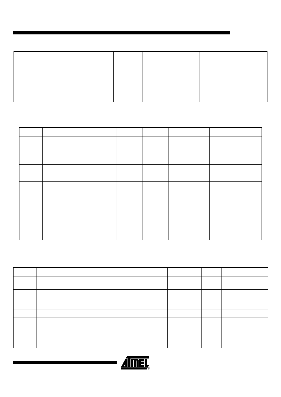
Notes:
1. Capacitor: X7R type or X5R type, max ESR value is 30m
Ω (100kHz-100MHz),
Replacing 3.3µF by 2.2µF in parrallel with 1µF is better for ESR and noise reduction.
Notes:
1. Capacitor: X7R type or X5R type, max ESR value is 30m
Ω (100kHz-100MHz),
Replacing 3.3µF by 2.2µF in parrallel with 1µF is better for ESR and noise reduction.
T
VLH
CVCC 0 to Valid
140
110
130
100
250
250
250
250
μs
VCC = 3V, C
L
= 3.3µF
Icard =
65mA
Icard =
0mA
VCC = 3V, C
L
= 10µF
Icard =
60mA
Icard =
0mA
Table 22. Smart Card Class C
Symbol
Parameter
Min
Typ
Max
Unit
Test Conditions
CI
CC
Card Supply Current Capability
40
mA
VCC = 3V
CI
CC
_ovf
Card Supply Current Overflow:
ICCADJ = 0 (reset value)
ICCADJ = 1
45
mA
Spikes on CVCC
1.68
1.92
V
Vcardok up Vcardok high level threshold
1.75
1.8
V
Vcardok
down
Vcardok low level threshold
1.7
1.75
V
T
VHL
CVCC valid to 0
180
300
μs
Icard = 0, C
L
= 10
μ
F
(1)
CVCC = 1.8V to 0.4V
T
VLH
CVCC 0 to valid
200
100
50
60
300
150
80
100
μs
Icard = 40mA, C
L
= 10
μ
F
(1)
Icard = 0, C
L
= 10
μ
F
(1)
Icard = 40mA, C
L
= 3.3
μ
F
(1)
Icard = 0, C
L
= 3.3
μ
F
(1)
CVCC = 0.4 to VCARDOK
Table 21. Smart Card Class B
Symbol
Parameter
Min
Typ
Max
Unit
Test Conditions
Table 23. Smart Card Clock (CCLK pin)
Symbol
Parameter
Min
Typ
Max
Unit
Test Conditions
V
OL
Output Low-voltage
0
0.4
V
I
OL
= -200
μ
A CLASS
A&B&C
V
OH
Output High Voltage
CVCC - 0.45
0.7CVCC
CVCC
CVCC
V
I
OH
= +200
μ
A CLASS
A&B
CLASS C
I
OS
Short Circuit Current
-30
30
mA
Short to GND or CVCC
t
R
t
F
Rise and Fall time
16
22.5
50
ns
C
L =
30 pF CLASS A
C
L =
30 pF CLASS B
C
L =
30 pF CLASS C
measurement between
10% and 90% of CVCC