At83c24 – Rainbow Electronics AT83C24NDS User Manual
Page 24
24
4234F–SCR–10/05
AT83C24
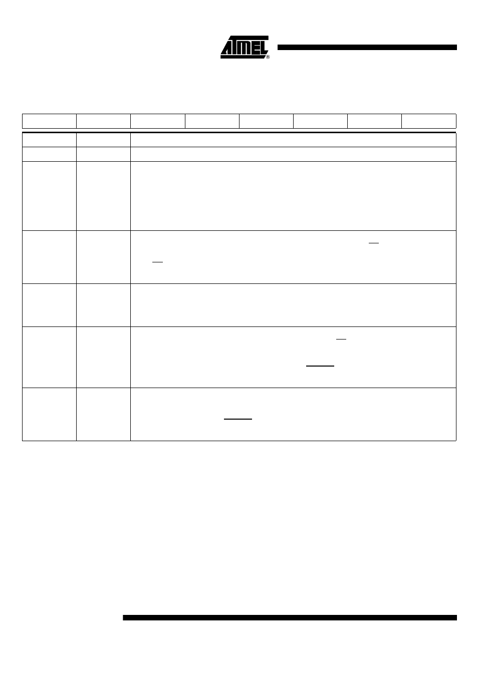
Table 10. CONFIG4 (Config Byte 4)
7
6
5
4
3
2
1
0
X
X
X
STEPREG
INT_PULLUP
POWERMON
IT_SEL
CRST_SEL
Bit Number
Bit Mnemonic
Description
7-5
X-X-X
These bits should not be set.
4
STEPREG
Step Regulator mode
Clear this bit to enable the automatic step-up converter (CVCC is stable even if VCC is not higher than CVCC).
Set this bit to permanently disable the step-up converter (CVCC is stable only if VCC is sufficiently higher than
CVCC).
This bit must be set before activating the DC/DC converter if no external coil is present.
The reset value is 0.
This bit must always be set if no external coil is used
3
INT_PULLUP
Internal pull-up
Set this bit to activate the internal pull-up (connected internally to EVCC) on PRES/INT pin.
Clear this bit to deactivate the internal pull-up.
PRES/INT is an open drain output with a programmable internal pull up.
The reset value is 0.
2
POWERMON
Power monitor
Set this bit to monitor any glitch on the Digital Supply Voltage (DVCC) of the AT83C24.
Clear this bit to monitor any glitch on VCC.
The reset value is 0.
1
IT_SEL
Interrupt Select
Set this bit to disable INSERT and VCARD_INT interrupts. Then PRES/INT is pulled up when a card is present
and no error is detected.
Clear this bit to have all the interrupt sources enabled and active Low.
IT_SEL must be set to enable a hardware activation with CMDVCC.
The reset value is 0.
0
CRST_SEL
Card Reset Selection
Set this bit to have the CRST pin driven by hardware through the A1 pin (only with hardware activation).
Clear this bit to have the CRST pin driven by software through the CARDRST bit.
CRST_SEL must be set when CMDVCC is used (hardware activation).
The reset value is 0.