At83c24 – Rainbow Electronics AT83C24NDS User Manual
Page 26
26
4234F–SCR–10/05
AT83C24
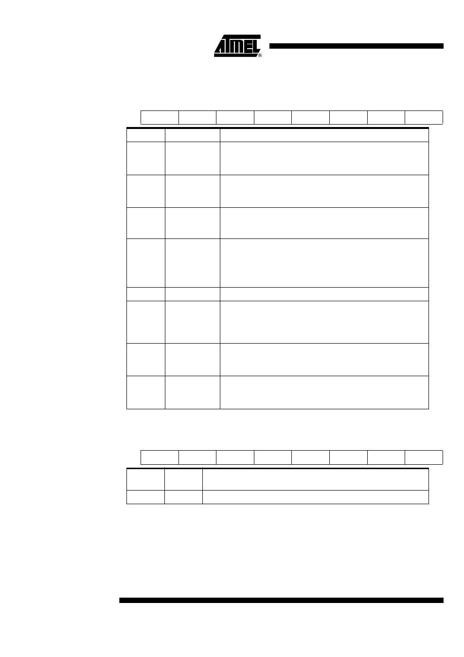
Reset value = 0x00000001
Table 12. STATUS (Status Byte)
7
6
5
4
3
2
1
0
CC8
CC4
CARDIN
VCARDOK
X
VCARD_INT
CRST
CIO
Bit Number
Bit Mnemonic
Description
7
CC8
Card CC8
This bit provides the actual level on the CC8 pin when read.
The reset value is 0.
6
CC4
Card CC4
This bit provides the actual level on the CC4 pin when read.
The reset value is 0.
5
CARDIN
Card Presence Status
This bit is set when a card is detected.
It is cleared otherwise.
4
VCARD_OK
Card Voltage Status
This bit is set by the DCDC when the output voltage remains within the
voltage range specified by VCARD[1:0] bits.
It is cleared otherwise.
The reset value is 0.
3
X
This bit should not be set.
2
VCARD_INT
Card voltage interrupt
This bit is set when VCARD_OK bit is set.
This bit is cleared when read by the microcontroller.
The reset value is 0.
1
CRST
Card RST
This bit provides the actual level on the CRST pin when read.
The reset value is 0.
0
CIO
Card I/O
This bit provides the actual level on the CIO pin when read.
The reset value is 0.
Table 13. TIMER 1 (Timer MSB)
7
6
5
4
3
2
1
0
Bit 15
Bit 14
Bit 13
Bit 12
Bit 11
Bit 10
Bit 9
Bit 8
Bit
Number
Bit
Mnemonic
Description
7 - 0
Bits 15 - 8
Timer MSB (bits 15 to 8)