Transparent mode, At83c24 – Rainbow Electronics AT83C24NDS User Manual
Page 17
17
4234F–SCR–10/05
AT83C24
•
VCARDERR bit is set by hardware (or by software)
•
INSERT is set and CARDIN is cleared (card extraction)
•
SHUTDOWN is set by software
•
CMDVCC goes from Low to High
•
Power fail on VCC (see POWERMON bit in CONFIG4 register)
•
Reset pin going low
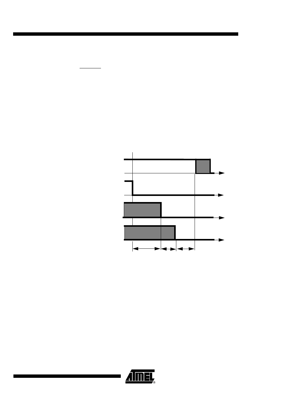
It is a self-timed sequence which cannot be interrupted when started (see Figure 13). Each step
is separated by a delay based on Td equal to 8 periods of the DC/DC clock, typically 2 µs:
1.
T0: CARDRST is cleared, SHUTDOWN bit set.
2.
T0 + 5 x Td:CARDCK is cleared, CKSTOP, CARDIO and IODIS are set.
3.
T0 + 6 x Td: CARDIO is cleared.
4.
T0 + 7 x Td: VCARD[1-0] = 00.
Figure 13. Deactivation Sequence
Notes:
1. Setting ICARDERR by software does not trigger a deactivation. VCARDERR can be used to
deactivate the card by software.
2. t1=5 to 5.5*Td, and t2=0.5*Td to Td.
Transparent Mode
If the microcontroller outputs ISO 7816 signals, a transparent mode allows to connect RST/CLK
and I/O/C4/C8 signals after an electrical level control. The AT83C24 level shifters adapt the card
signals to the smart card voltage selection.
The CRST and CCLK microcontroller signals can be respectively connected to the A1/RST and
A2/CK pins.
The CRST_SEL bit (in CONFIG4 register) selects standard or transparent configuration for the
CRST pin. CKS in CONFIG2 allows to select standard or transparent configuration for the CCLK
pin. So CCLK and CRST are independent. A2/CK to A0/3V inputs always give the TWI address
at reset. The A0/3V pin can be used for TWI addressing and easily connect two AT83C24
devices on the same TWI bus.
CVCC
CRST
CCLK
CIO,
Td
CC4,
CC8
t1
t2