At83c24 – Rainbow Electronics AT83C24NDS User Manual
Page 23
23
4234F–SCR–10/05
AT83C24
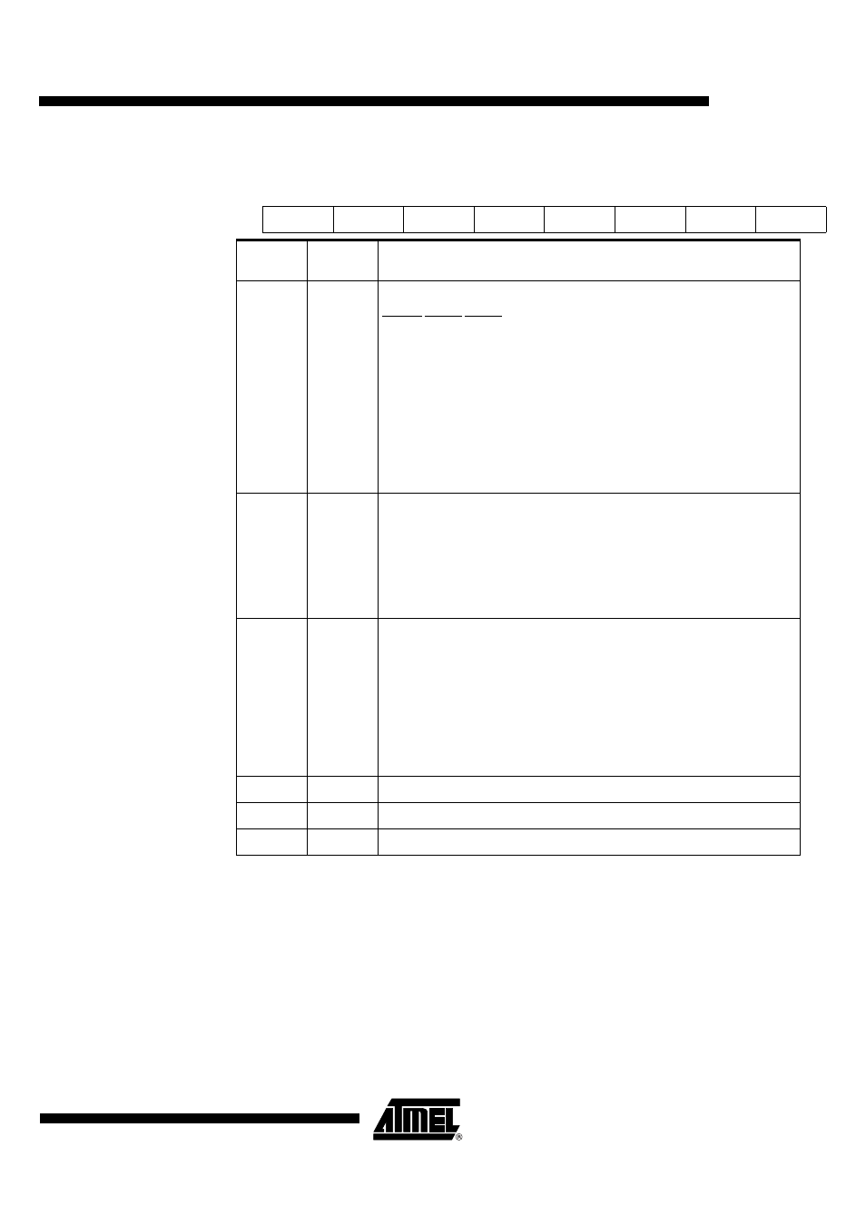
Table 9. CONFIG3 (Config Byte 3)
7
6
5
4
3
2
1
0
EAUTO
VEXT1
VEXT0
ICCADJ
LP
X
X
X
Bit
Number
Bit
Mnemonic
Description
7-5
EAUTO
VEXT1
VEXT0
EVCC voltage configuration:
EAUTO VEXT1 VEXT0
0
0
0 EVCC = 0 the regulator is switched off.
0 0
1EVCC
=
2.3V
0
1
0 EVCC = 1.8V
0
1
1 EVCC = 2.7V
1
X
X EVCC voltage is the level detected on I/O input pin.
if EVCC is supplied from the external EVCC pin, the user can switch off the
internal EVCC regulator to decrease the consumption.
If EVCC is switched off, and no external EVCC is supplied, the AT83C24 is
inactive until a hardware reset is done.
The reset value is 100.
4
ICCADJ
CI
CC
overflow adjust
This bit controls the DC/DC sensitivity to any overflow current .
Set this bit to decrease the DC/DC sensitivity (CI
CC_ovf
is increased by about
20%, see Electrical Characteristics). The start of the DC/DC with a high current
load is easier.
Clear this bit to have a normal configuration.
The reset value is 0.
3
LP
Low-power Mode
Set this bit to enable low-power mode during shutdown mode (pulsed mode
activated).
Clear this bit to disable low-power mode during shutdown mode.
The activation reference is the following:
• First select the Low-power mode by setting LP bit.
• The activation of SHUTDOWN bit can then be done.
This bit as no effect when SHUTDOWN bit is cleared.
The reset value is 0.
2
X
This bit should not be set.
1
X
This bit should not be set.
0
X
This bit should not be set.