Power modes, At83c24 – Rainbow Electronics AT83C24NDS User Manual
Page 18
18
4234F–SCR–10/05
AT83C24
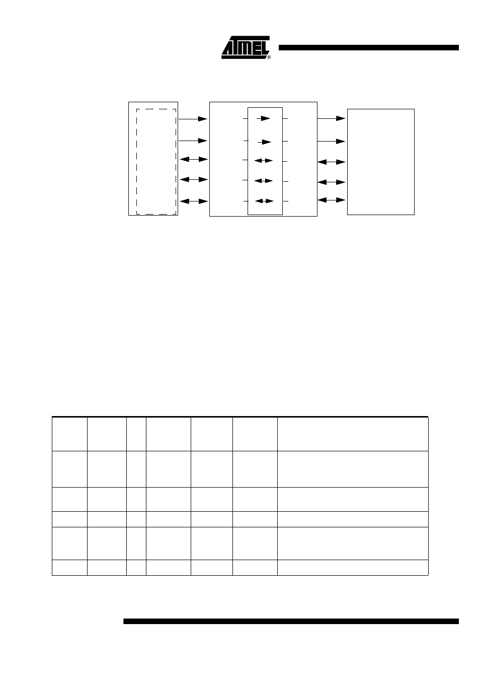
Figure 14. Transparent Mode Description
Power Modes
Two power-down modes are available to reduce the AT83C24 power consumption (see STUT-
DOWN bit in CONFIG1 register and LP bits in CONFIG3 register).
To enter in the mode number 4 (see Table 5), the sequence is the following:
–
First select the Low-power mode by setting the LP bit
–
The activation of the SHUTDOWN bit can then be done.
The AT83C24 exits Power-down if a software/hardware reset is done or if SHUTDOWN bit is
cleared. The AT83C24 is then active immediately.
Either a hardware reset or a TWI command clearing the SHUTDOWN bit can cause an exit from
Power-down. The internal registers retain their value during the shutdown mode.
In Power-down mode, the device is sleeping and waiting for a wake up condition.
To reduce power consumption, the User should stop the clock on the CLK input after setting the
SHUTDOWN bit. The clock can be enabled again just before exiting SHUTDOWN (at least 10
µs before a START bit on SDA).
CCLK
CRST
CIO
I/O
A2/CK
A1/RST
AT83C24
SMART CARD
CRST
CCLK
CC4
Microcontroller
CC8
CIO
C4
C8
CC4
CC8
Table 5. Power Modes Description
Mode
Number
Shutdown
Bit
LP
Bit
STEPREG
VCARD[1:0]
Typical
Supply
Current
Description
1
0
X
0
11
160 mA
30 mA
Step up mode: VCC = 3V, CVCC = 5V,
Icard
= 65mA
Icard
= 0
2
0
X
1
11
70 mA
Regulator mode: VCC = 5.25V, CVCC = 5V,
Icvcc = 65mA
3
0
X
X
00
3 mA
DC/DC off, CLK = 10MHz, VCC=3V to 5V
4
1
0
X
00
90 µA
The TWI interface of the AT83C24 is active
but its analog blocs are switched off to reduce
the consumption
5
1
1
X
00
30 µA
Pulsed mode of the internal 3V logic regulator