Ac parameters – Rainbow Electronics T89C5115 User Manual
Page 95
95
T89C5115
4128A–8051–04/02
AC Parameters
Explanation of the AC
Symbols
Each timing symbol has 5 characters. The first character is always a “T” (stands for
time). The other characters, depending on their positions, stand for the name of a signal
or the logical status of that signal. The following is a list of all the characters and what
they stand for.
Example: T
AVLL
= Time for Address Valid to ALE Low.
T
LLPL
= Time for ALE Low to PSEN Low.
T
A
= -40
°
C to +85
°
C; V
SS
= 0V; V
CC
= 5V
±
10%; F = 0 to 40 MHz.
T
A
= -40
°
C to +85
°
C; V
SS
= 0V; V
CC
= 5V
±
10%.
( Load Capacitance for all outputs = 60 pF.)
Table 70 and Table 74 give the description of each AC symbols.
Table 71, Table 72 and Table 73 give for each range the AC parameter.
Table 72 gives the frequency derating formula of the AC parameter for each speed
range description. To calculate each AC symbols. Take the x value and use this value in
the formula.
Example: T
LLIV
and 20 MHz, Standard clock.
x = 30 ns
T = 50 ns
T
CCIV
= 4T - x = 170 ns
Serial Port Timing – Shift
Register Mode
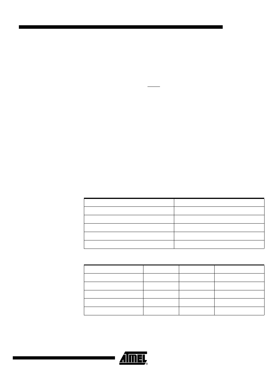
Table 70. Symbol Description (F = 40 MHz)
Table 71. AC Parameters for a Fix Clock (F = 40 MHz)
Symbol
Parameter
T
XLXL
Serial port clock cycle time
T
QVHX
Output data set-up to clock rising edge
T
XHQX
Output data hold after clock rising edge
T
XHDX
Input data hold after clock rising edge
T
XHDV
Clock rising edge to input data valid
Symbol
Min
Max
Units
T
XLXL
300
ns
T
QVHX
200
ns
T
XHQX
30
ns
T
XHDX
0
ns
T
XHDV
117
ns