Pca interrupt, Pca capture mode – Rainbow Electronics T89C5115 User Manual
Page 69
69
T89C5115
4128A–8051–04/02
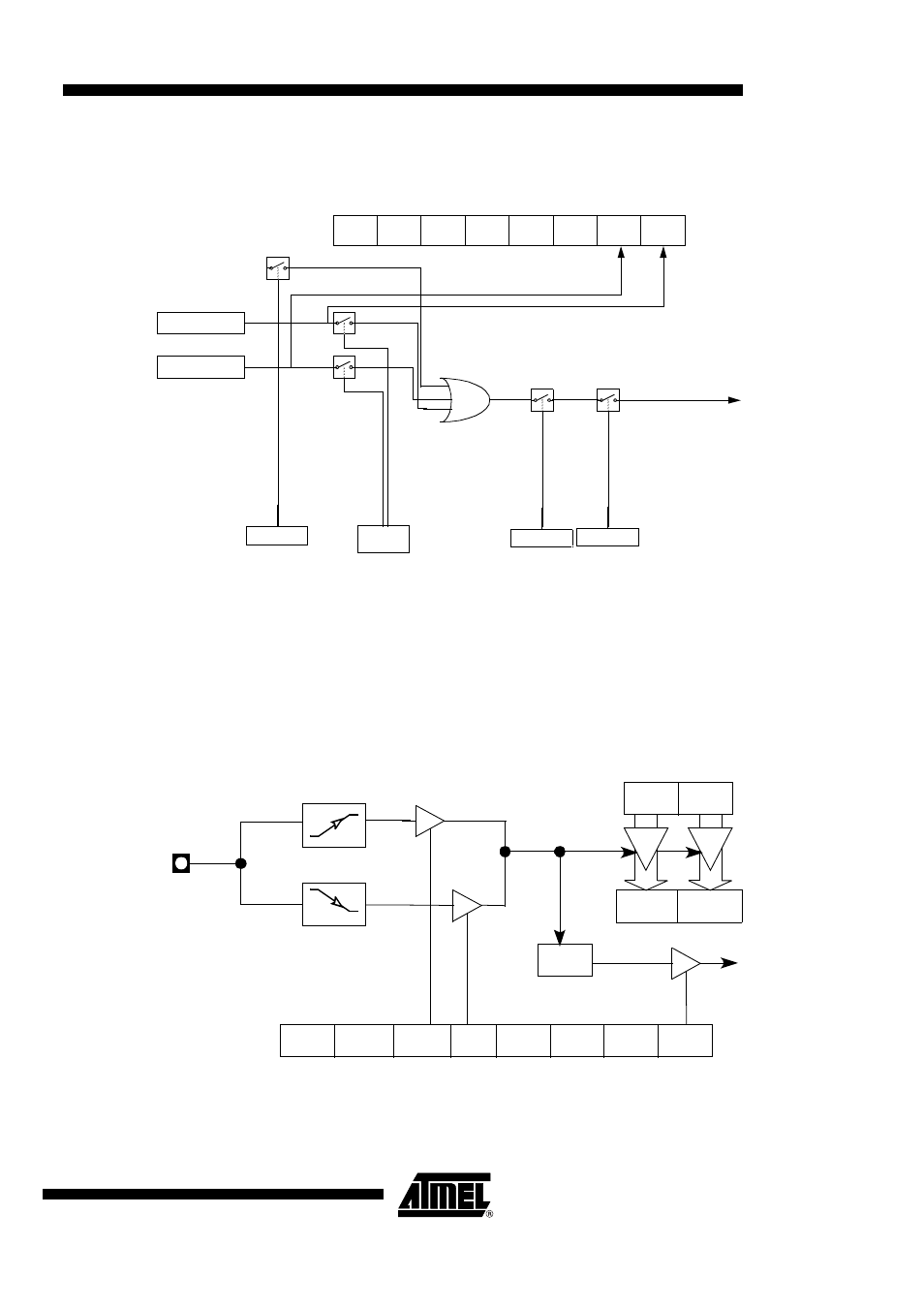
PCA Interrupt
Figure 31. PCA Interrupt System
PCA Capture Mode
To use one of the PCA modules in capture mode either one or both of the CCAPM bits
CAPN and CAPP for that module must be set. The external CEX input for the module
(on port 1) is sampled for a transition. When a valid transition occurs the PCA hardware
loads the value of the PCA counter registers (CH and CL) into the module’s capture reg-
isters (CCAPnL and CCAPnH). If the CCFn bit for the module in the CCON SFR and the
ECCFn bit in the CCAPMn SFR are set then an interrupt will be generated.
Figure 32. PCA Capture Mode
CF
CR
CCON
0xD8
CCF1
CCF0
Module 1
Module 0
PCA Timer/Counter
To Interrupt
EC
IEN0.6
EA
IEN0.7
ECF
CMOD.0
ECCFn
CCAPMn.0
CEXn
n = 0, 1
PCA Counter
CH
(8bits)
CL
(8bits)
CCAPnH CCAPnL
CCFn
CCON Reg
PCA
Interrupt
Request
-
7
CCAPMn Register (n = 0, 1)
0
ECCFn
CAPNn000
0CAPPn
- MAX5151 (16 pages)
- MAXQ3108 (64 pages)
- MAX5661 (39 pages)
- MAX6691 (7 pages)
- MAX5362 (12 pages)
- ADC10158 (26 pages)
- MAX8922L (14 pages)
- MAX8596Z (8 pages)
- MAX7491 (18 pages)
- MAX15040 (15 pages)
- MAX5177 (16 pages)
- ADC08138 (22 pages)
- MAX5961 (42 pages)
- T89C51RD2 (86 pages)
- MAX16055 (9 pages)
- MAX6659 (17 pages)
- ADC0820 (20 pages)
- MAX6678 (19 pages)
- MAX8884Z (15 pages)
- MAX16915 (9 pages)
- MAX8620 (18 pages)
- MAX5144 (12 pages)
- MAX6670 (8 pages)
- MAX8760 (39 pages)
- W78C32C (14 pages)
- MX7533 (8 pages)
- MAX8727 (13 pages)
- MAX9053 (15 pages)
- W78C54 (16 pages)
- MAX8614B (15 pages)
- W90N740 (219 pages)
- MAX6626 (13 pages)
- ADC10738 (30 pages)
- MAX17000 (31 pages)
- MAX5051 (21 pages)
- MAXQ1004 (18 pages)
- MAX6871 (51 pages)
- MX7847 (12 pages)
- MAX6608 (6 pages)
- MAX17083 (15 pages)
- MAX6641 (17 pages)
- MAX5251 (16 pages)
- MAX6338 (8 pages)
- MAX6690 (16 pages)
- MAX8668 (18 pages)