Rainbow Electronics T89C5115 User Manual
Page 36
36
T89C5115
4128A–8051–04/02
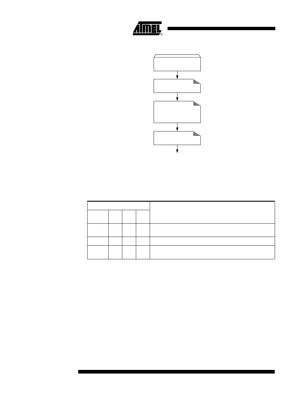
Figure 15. Reading Procedure
Flash Protection from Parallel
Programming
The three lock bits in Hardware Security Byte (see "In-System Programming" section)
are programmed according to Table 22 provide different level of protection for the on-
chip code and data located in FM0 and FM1.
The only way to write this bits are the parallel mode. They are set by default to level 3.
Table 22. Program Lock bit
Program Lock bits
U: unprogrammed
P: programmed
WARNING: Security level 2 and 3 should only be programmed after Flash and Core
verification.
Preventing Flash Corruption
See paragraph in the "Power Management" section, page 17.
Flash Spaces Reading
Flash Spaces Mapping
FCON= 00000xx0b
Data Read
DPTR= Address
ACC= 0
Exec: MOVC A, @A+DPTR
Clear Mode
FCON = 00h
Program Lock Bits
Protection Description
Security
level
LB0
LB1
LB2
1
U
U
U
No program lock features enabled. MOVC instruction executed from
external program memory returns non encrypted data.
2
P
U
U
Parallel programming of the Flash is disabled.
3
U
P
U
Same as 2, also verify through parallel programming interface is
disabled.