Figure 41, Figure 42.), Figure 43 – Rainbow Electronics T89C5115 User Manual
Page 93
93
T89C5115
4128A–8051–04/02
5. Under steady state (non-transient) conditions, I
OL
must be externally limited as fol-
lows:
Maximum I
OL
per port pin: 10 mA
Maximum I
OL
per 8-bit port:
Ports 1, 2 and 3: 15 mA
Maximum total I
OL
for all output pins: 71 mA
If I
OL
exceeds the test condition, V
OL
may exceed the related specification. Pins are
not guaranteed to sink current greater than the listed test conditions.
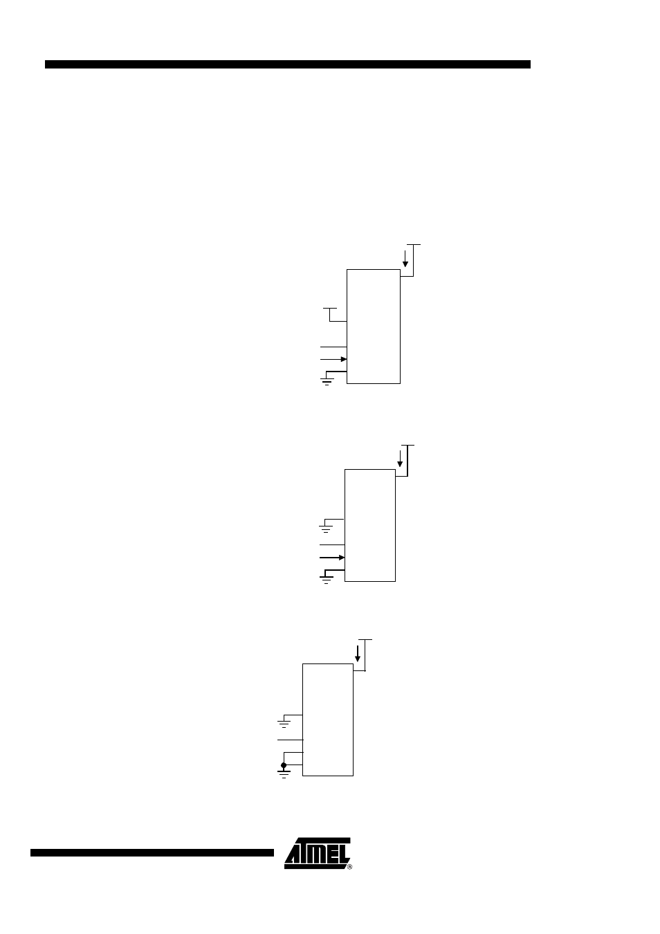
Figure 41. I
CC
Test Condition, Active Mode
Figure 42. I
CC
Test Condition, Idle Mode
Figure 43. I
CC
Test Condition, Power-down Mode
V
CC
I
CC
(NC)
CLOCK
SIGNAL
V
CC
All other pins are disconnected.
RST
XTAL2
XTAL1
V
SS
V
CC
RST
XTAL2
XTAL1
V
SS
V
CC
I
CC
(NC)
V
CC
All other pins are disconnected.
CLOCK
SIGNAL
RST
XTAL2
XTAL1
V
SS
V
CC
I
CC
(NC)
V
CC
All other pins are disconnected
See also other documents in the category Rainbow Electronics Sensors:
- MAX5151 (16 pages)
- MAXQ3108 (64 pages)
- MAX5661 (39 pages)
- MAX6691 (7 pages)
- MAX5362 (12 pages)
- ADC10158 (26 pages)
- MAX8922L (14 pages)
- MAX8596Z (8 pages)
- MAX7491 (18 pages)
- MAX15040 (15 pages)
- MAX5177 (16 pages)
- ADC08138 (22 pages)
- MAX5961 (42 pages)
- T89C51RD2 (86 pages)
- MAX16055 (9 pages)
- MAX6659 (17 pages)
- ADC0820 (20 pages)
- MAX6678 (19 pages)
- MAX8884Z (15 pages)
- MAX16915 (9 pages)
- MAX8620 (18 pages)
- MAX5144 (12 pages)
- MAX6670 (8 pages)
- MAX8760 (39 pages)
- W78C32C (14 pages)
- MX7533 (8 pages)
- MAX8727 (13 pages)
- MAX9053 (15 pages)
- W78C54 (16 pages)
- MAX8614B (15 pages)
- W90N740 (219 pages)
- MAX6626 (13 pages)
- ADC10738 (30 pages)
- MAX17000 (31 pages)
- MAX5051 (21 pages)
- MAXQ1004 (18 pages)
- MAX6871 (51 pages)
- MX7847 (12 pages)
- MAX6608 (6 pages)
- MAX17083 (15 pages)
- MAX6641 (17 pages)
- MAX5251 (16 pages)
- MAX6338 (8 pages)
- MAX6690 (16 pages)
- MAX8668 (18 pages)