Interrupt system, Introduction – Rainbow Electronics T89C5115 User Manual
Page 84
84
T89C5115
4128A–8051–04/02
Interrupt System
Introduction
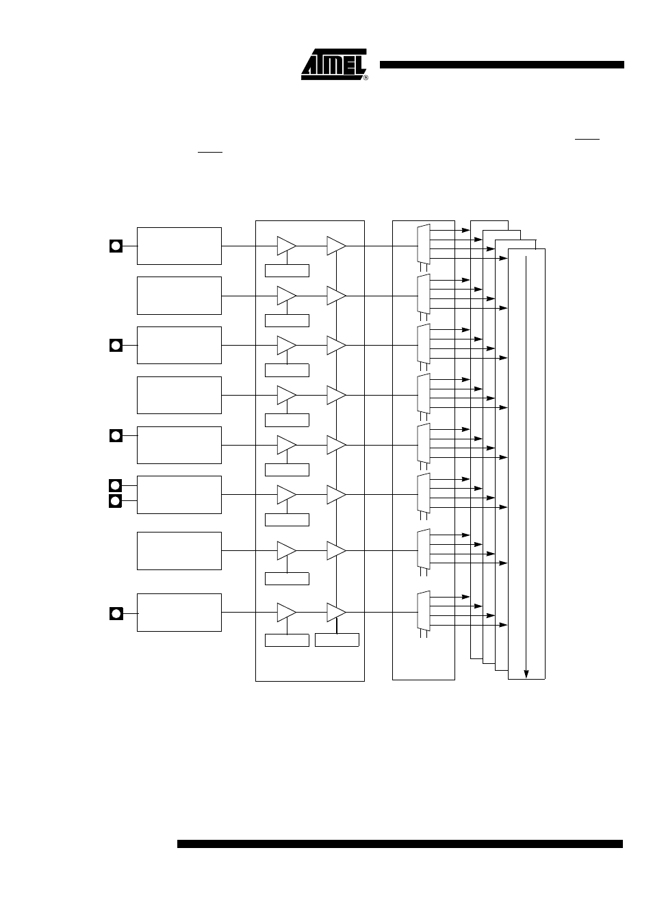
The T89C5115 has a total of 8 interrupt vectors: two external interrupts (INT0 and
INT1), three timer interrupts (timers 0, 1 and 2), a serial port interrupt, a PCAand an
ADC. These interrupts are shown below.
Figure 40. Interrupt Control System
Each of the interrupt sources can be individually enabled or disabled by setting or clear-
ing a bit in the Interrupt Enable register. This register also contains a global disable bit
which must be cleared to disable all the interrupts at the same time.
Each interrupt source can also be individually programmed to one of four priority levels
by setting or clearing a bit in the Interrupt Priority registers. The Table below shows the
bit values and priority levels associated with each combination.
EX0
IEN0.0
00
01
10
11
External
Interrupt 0
INT0#
EX1
IEN0.2
External
Interrupt 1
INT1#
ET0
IEN0.1
Timer 0
EC
IEN0.6
PCA
ET1
IEN0.3
Timer 1
ES
IEN0.4
UART
Interrupt Enable
Lowest Priority Interrupts
Highest
Priority Enable
00
01
10
11
00
01
10
11
00
01
10
11
00
01
10
11
00
01
10
11
Priority
Interrupts
AIN1:0
IPH/L
Timer 2
00
01
10
11
ET2
IEN0.5
TxD
RxD
CEX0:1
ADC
00
01
10
11
EADC
IEN1.1
EA
IEN0.7