Rainbow Electronics T89C5115 User Manual
Page 5
5
T89C5115
4128A–8051–04/02
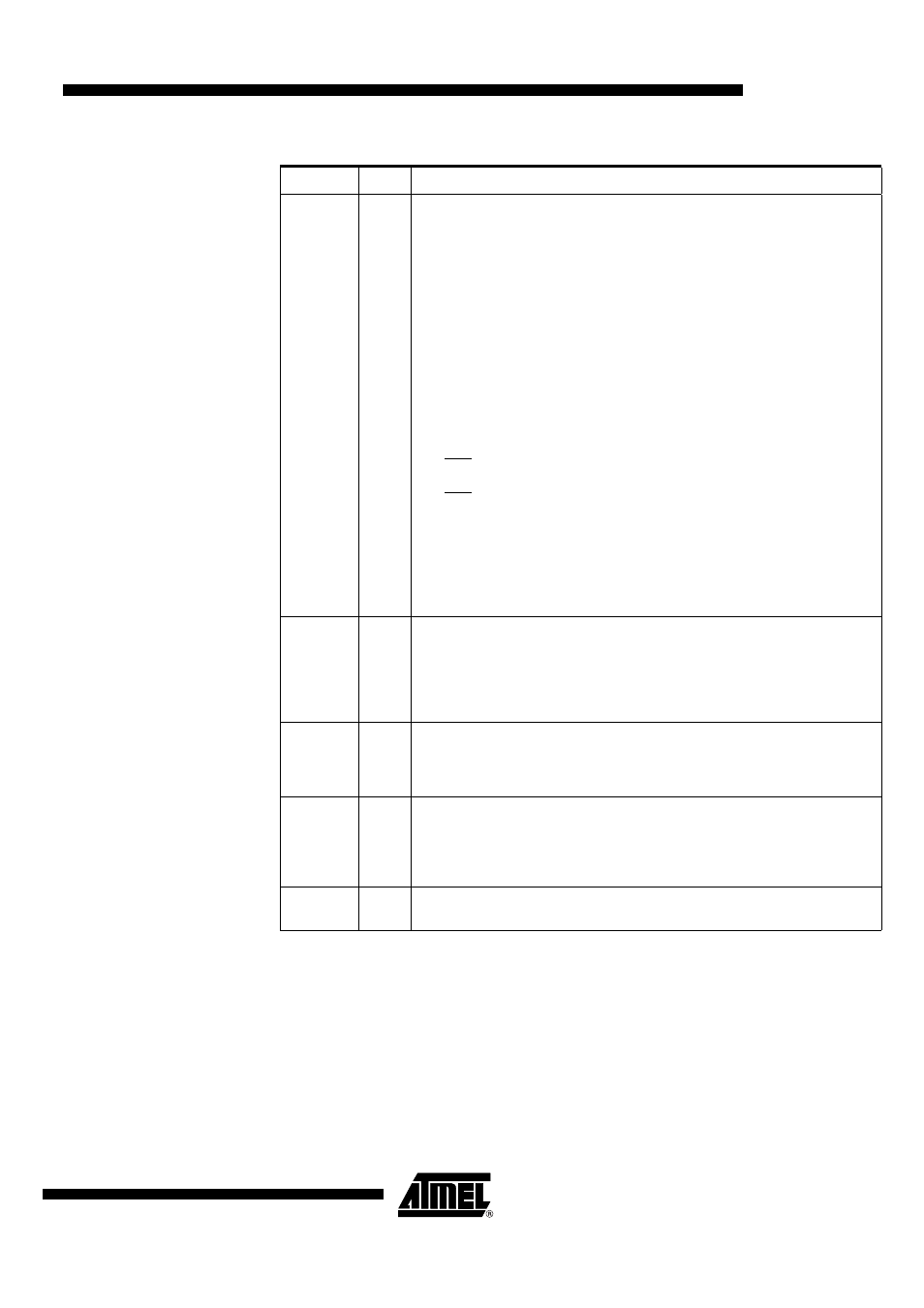
P3.0:7
I/O
Port 3:
Is an 8-bit bi-directional I/O port with internal pull-ups. Port 3 pins that have 1’s
written to them are pulled high by the internal pull-up transistors and can be used as
inputs in this state. As inputs, Port 3 pins that are being pulled low externally will be a
source of current (I
IL
, see section "Electrical Characteristic") because of the internal
pull-ups.
The output latch corresponding to a secondary function must be programmed to one
for that function to operate (except for TxD ). The secondary functions are assigned
to the pins of port 3 as follows:
P3.0/RxD:
Receiver data input (asynchronous) or data input/output (synchronous) of the serial
interface
P3.1/TxD:
Transmitter data output (asynchronous) or clock output (synchronous) of the serial
interface
P3.2/INT0:
External interrupt 0 input/timer 0 gate control input
P3.3/INT1:
External interrupt 1 input/timer 1 gate control input
P3.4/T0:
Timer 0 counter input
P3.5/T1:
Timer 1 counter input
It can drive CMOS inputs without external pull-ups.
P4.0:1
I/O
Port 4:
Is an 2-bit bi-directional I/O port with internal pull-ups. Port 4 pins that have 1’s
written to them are pulled high by the internal pull-ups and can be used as inputs in
this state. As inputs, Port 4 pins that are being pulled low externally will be a source
of current (IIL, on the datasheet) because of the internal pull-up transistor.
It can drive CMOS inputs without external pull-ups.
RESET
I/O
Reset:
A high level on this pin during two machine cycles while the oscillator is running
resets the device. An internal pull-down resistor to VSS permits power-on reset
using only an external capacitor to VCC.
XTAL1
I
XTAL1:
Input of the inverting oscillator amplifier and input of the internal clock generator
circuits. To drive the device from an external clock source, XTAL1 should be driven,
while XTAL2 is left unconnected. To operate above a frequency of 16 MHz, a duty
cycle of 50% should be maintained.
XTAL2
O
XTAL2:
Output from the inverting oscillator amplifier.
Table 1. Pin Description (Continued)
Pin Name
Type
Description