Detailed description, Pin description (continued), Table 1. component values – Rainbow Electronics MAX9995 User Manual
Page 9
Detailed Description
The MAX9995 dual, high-linearity, downconversion
mixer provides 6.1dB gain and +25.6dBm IIP3, with a
9.8dB noise figure. Integrated baluns and matching cir-
cuitry allow 50
Ω single-ended interfaces to the RF and
LO ports. A single-pole, double-throw (SPDT) LO
switch provides 50ns switching time between LO
inputs, with 50dB LO-to-LO isolation. Furthermore, the
integrated LO buffer provides a high drive level to the
mixer core, reducing the LO drive required at the
MAX9995’s inputs to -3dBm. The IF port incorporates a
differential output, which is ideal for providing
enhanced 2RF-2LO performance.
Specifications are guaranteed over broad frequency
ranges to allow for use in UMTS/WCDMA and
2G/2.5G/3G DCS1800, PCS1900, and cdma2000 base
stations. The MAX9995 is specified to operate over an
RF input range of 1700MHz to 2200MHz, an LO range
of 1400MHz to 2000MHz, and an IF range of 40MHz to
350MHz. Operation beyond this is possible; however,
performance is not characterized. This device can
operate in high-side LO injection applications with an
extended LO range, but performance degrades as f
LO
continues to increase. For a device with better high-
side performance, contact the factory. This device is
available in a compact 6mm x 6mm, 36-pin thin QFN
package with an exposed paddle.
RF Input and Balun
The MAX9995’s two RF inputs (RFMAIN and RFDIV) are
internally matched to 50
Ω, requiring no external match-
ing components. DC-blocking capacitors are required
as the inputs are internally DC shorted to ground
through the on-chip baluns. Input return loss is typically
14dB over the entire RF frequency range of 1700MHz
to 2200MHz.
LO Input, Switch, Buffer, and Balun
The mixers can be used for either high-side or low-side
injection applications with an LO frequency range of
1400MHz to 2000MHz. For a device with an LO fre-
quency range of 1900MHz to 2400MHz, contact the
factory. As an added feature, the MAX9995 includes an
MAX9995
Dual, SiGe, High-Linearity, 1700MHz to 2200MHz
Downconversion Mixer with LO Buffer/Switch
_______________________________________________________________________________________
9
PIN
NAME
DESCRIPTION
27
LO2
Local Oscillator 2 Input. This input is internally matched to 50
Ω. Requires an input DC-blocking
capacitor.
29
LO_ADJ_M
LO Main Amplifier Bias Control. Connect a 392
Ω resistor from this pin to ground to set the bias
current for the main LO amplifier.
31
IND_EXTM
Connect a 10nH inductor from this pin to ground to increase the RF-IF and LO-IF isolation.
32, 33
IFM-, IFM+
Main Mixer Differential IF Output. Connect pullup inductors from each of these pins to V
CC
(see the Typical Application Circuit).
35
IFM_SET
IF Main Amplifier Bias Control. Connect a 1.2k
Ω resistor from this pin to ground to set the bias
current for the main IF amplifier.
Exposed Paddle
GND
Exposed Ground Plane. This paddle affects RF performance and provides heat dissipation. The
paddle must be connected to ground.
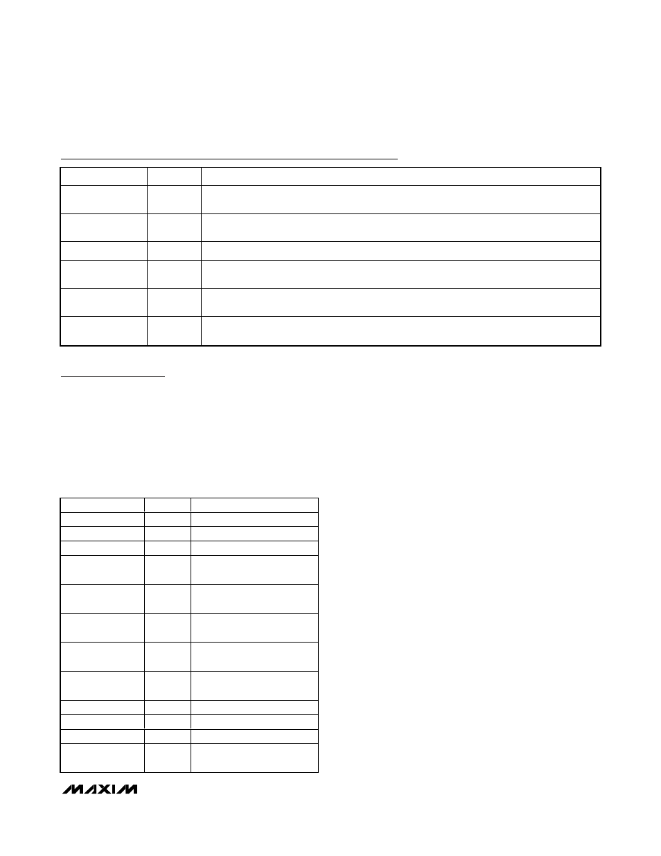
Pin Description (continued)
Table 1. Component Values
COMPONENT
VALUE
DESCRIPTION
C1, C8
4pF
Microwave capacitors (0402)
C2, C7
10pF
Microwave capacitors (0402)
C3, C6
0.033µF
Microwave capacitors (0603)
C4, C5, C14, C16
22pF
Microwave capacitors (0402)
C9, C13, C15,
C17, C18
0.01µF
Microwave capacitors (0402)
C10, C11, C12,
C19, C20, C21
150pF
Microwave capacitors (0603)
L1, L2, L4, L5
330nH
Wire-wound high-Q inductors
(0805)
L3, L6
10nH
Wire-wound high-Q inductors
(0603)
R1, R4
1.21k
Ω
±1% resistors (0402)
R2, R5
392
Ω
±1% resistors (0402)
R3, R6
10
Ω
±1% resistors (1206)
T1, T2
4:1
(200:50)
IF baluns