Absolute maximum ratings, Dc electrical characteristics, Ac electrical characteristics – Rainbow Electronics MAX9995 User Manual
Page 2
MAX9995
Dual, SiGe, High-Linearity, 1700MHz to 2200MHz
Downconversion Mixer with LO Buffer/Switch
2
_______________________________________________________________________________________
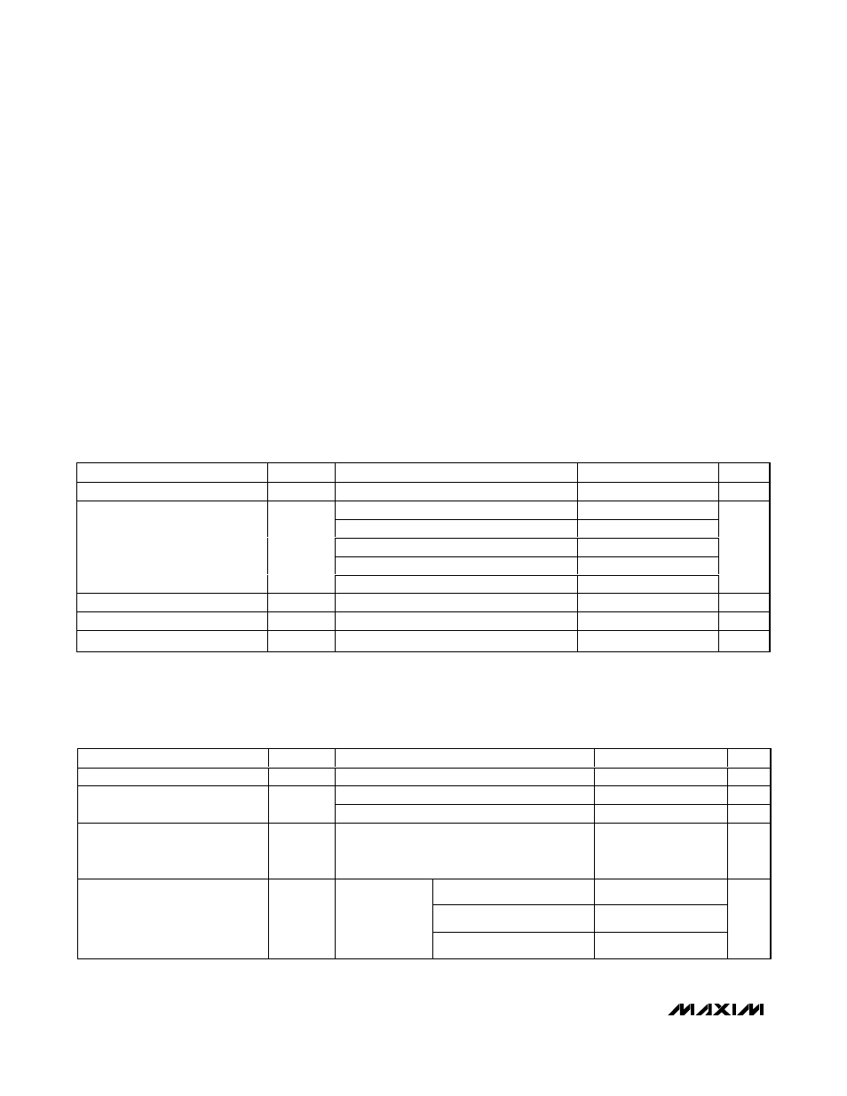
ABSOLUTE MAXIMUM RATINGS
Stresses beyond those listed under “Absolute Maximum Ratings” may cause permanent damage to the device. These are stress ratings only, and functional
operation of the device at these or any other conditions beyond those indicated in the operational sections of the specifications is not implied. Exposure to
absolute maximum rating conditions for extended periods may affect device reliability.
V
CC
........................................................................-0.3V to +5.5V
LO1, LO2 to GND ...............................................................±0.3V
IFM_, IFD_, IFM_SET, IFD_SET, LOSEL,
LO_ADJ_M, LO_ADJ_D to GND.............-0.3V to (V
CC
+ 0.3V)
RFMAIN, RFDIV, and LO_ Input Power ..........................+20dBm
RFMAIN, RFDIV Current (RF is DC shorted to GND through
balun) ..................................................................................50mA
Continuous Power Dissipation (T
A
= +70°C)
36-Lead Thin QFN (derate 26mW/°C
above +70°C).............................................................2100mW
θ
JA
.................................................................................+38°C/W
θ
JC
................................................................................+7.4°C/W
Operating Temperature Range (Note A) ....T
C
= -40°C to +85°C
Maximum Junction Temperature Range..........................+150°C
Storage Temperature Range .............................-65°C to +150°C
Lead Temperature (soldering, 10s) .................................+300°C
DC ELECTRICAL CHARACTERISTICS
(Typical Application Circuit, no input RF or LO signals applied, V
CC
= 4.75V to 5.25V, T
C
= -40°C to +85°C. Typical values are at V
CC
= 5.0V, T
C
= +25°C, unless otherwise noted.)
PARAMETER
SYMBOL
CONDITIONS
MIN
TYP
MAX
UNITS
Supply Voltage
V
CC
4.75
5
5.25
V
Total supply current
332
380
V
CC
(pin 16)
82
90
V
CC
(pin 30)
97
110
IFM+/IFM- (total of both)
70
90
Supply Current
I
CC
IFD+/IFD- (total of both)
70
90
mA
LOSEL Input High Voltage
V
IH
2
V
LOSEL Input Low Voltage
V
IL
0.8
V
LOSEL Input Current
I
IL
and I
IH
-10
+10
µA
AC ELECTRICAL CHARACTERISTICS
(Typical Application Circuit, V
CC
= 4.75V to 5.25V, RF and LO ports are driven from 50
Ω sources, P
LO
= -3dBm to +3dBm, f
RF
=
1700MHz to 2200MHz, f
LO
= 1400MHz to 2000MHz, f
IF
= 200MHz, with f
RF
> f
LO
, T
C
= -40°C to +85°C. Typical values are at V
CC
=
5.0V, P
LO
= 0dBm, f
RF
= 1900MHz, f
LO
= 1700MHz, f
IF
= 200MHz, and T
C
= +25°C, unless otherwise noted.) (Notes 1, 2)
PARAMETER
SYMBOL
CONDITIONS
MIN
TYP
MAX
UNITS
RF Frequency
f
RF
(Note 7)
1700
2200
MHz
(Note 7)
1400
2000
MHz
LO Frequency
f
LO
(Contact factory) (Note 7)
1900
2400
MHz
IF Frequency
f
IF
Meeting RF and LO frequency ranges;
IF matching components affect the IF
frequency range (Note 7)
40
350
MHz
f
RF
= 1710MHz to 1875MHz
6
f
RF
= 1850MHz to 1910MHz
6.2
Conversion Gain
G
C
f
RF
= 2110MHz to 2170MHz
6.1
dB
Note A: T
C
is the temperature on the exposed paddle of the package.