Ac electrical characteristics (continued) – Rainbow Electronics MAX9995 User Manual
Page 3
MAX9995
Dual, SiGe, High-Linearity, 1700MHz to 2200MHz
Downconversion Mixer with LO Buffer/Switch
_______________________________________________________________________________________
3
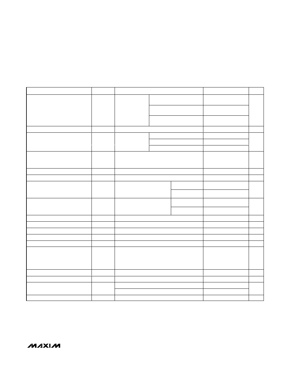
AC ELECTRICAL CHARACTERISTICS (continued)
(Typical Application Circuit, V
CC
= 4.75V to 5.25V, RF and LO ports are driven from 50
Ω sources, P
LO
= -3dBm to +3dBm, f
RF
=
1700MHz to 2200MHz, f
LO
= 1400MHz to 2000MHz, f
IF
= 200MHz, with f
RF
> f
LO
, T
C
= -40°C to +85°C. Typical values are at V
CC
=
5.0V, P
LO
= 0dBm, f
RF
= 1900MHz, f
LO
= 1700MHz, f
IF
= 200MHz, and T
C
= +25°C, unless otherwise noted.) (Notes 1, 2)
PARAMETER
SYMBOL
CONDITIONS
MIN
TYP
MAX
UNITS
f
RF
= 1710MHz to 1875MHz
±0.5
±1
f
RF
= 1850MHz to 1910MHz
±0.5
±1
Gain Variation from Nominal
V
CC
= 5.0V,
T
C
= +25°C,
P
LO
= 0dBm,
P
RF
= -10dBm
(Note 3)
f
RF
= 2110MHz to 2170MHz
±0.5
±1
dB
Gain Variation with Temperature
±0.75
dB
f
RF
= 1710MHz to 1875MHz
9.7
f
RF
= 1850MHz to 1910MHz
9.8
Noise Figure
NF
No blockers
present
f
RF
= 2110MHz to 2170MHz
9.9
dB
Noise Figure (with Blocker)
8dBm blocker tone applied to RF port at
2000MHz, f
RF
= 1900MHz, f
LO
= 1710MHz,
P
LO
= -3dBm
22
dB
Input 1dB Compression Point
P
1dB
(Note 3)
9.5
12.6
dBm
Input Third-Order Intercept Point
IIP3
(Notes 3, 4)
23
25.6
dBm
P
RF
= -10dBm
66
2RF-2LO Spur Rejection
2 x 2
f
RF
= 1900MHz,
f
LO
= 1700MHz,
f
SPUR
= 1800MHz (Note 3)
P
RF
= -5dBm
61
dBc
P
RF
= -10dBm
70
88
3RF-3LO Spur Rejection
3 x 3
f
RF
= 1900MHz,
f
LO
= 1700MHz,
f
SPUR
= 1766.7MHz (Note 3)
P
RF
= -5dBm
60
78
dBc
Maximum LO Leakage at RF Port
f
LO
= 1400MHz to 2000MHz
-29
dBm
M axi m um 2LO Leakag e at RF P or t
f
LO
= 1400MHz to 2000MHz
-17
dBm
Maximum LO Leakage at IF Port
f
LO
= 1400MHz to 2000MHz
-25
dBm
Minimum RF to IF Isolation
f
RF
= 1700MHz to 2200MHz, f
IF
= 200MHz
37
dB
LO1-LO2 Isolation
P
LO1
= 0dBm, P
LO2
= 0dBm (Note 5)
40
50.5
dB
Minimum Channel-to-Channel
Isolation
P
RF
= -10dBm, RFMAIN (RFDIV)
power measured at IFDIV (IFMAIN),
relative to IFMAIN (IFDIV),
all unused parts terminated at 50
Ω
40
44
dB
LO Switching Time
50% of LOSEL to IF settled to within 2°
50
ns
RF Return Loss
14
dB
LO port selected
18
LO Return Loss
LO port unselected
21
dB
IF Return Loss
LO driven at 0dBm, RF terminated into 50
Ω
21
dB
Note 1: Guaranteed by design and characterization.
Note 2: All limits reflect losses of external components. Output measurements taken at IF outputs of Typical Application Circuit.
Note 3: Production tested.
Note 4: Two tones 3MHz spacing, -5dBm per tone at RF port.
Note 5: Measured at IF port at IF frequency. f
LO1
and f
LO2
are offset by 1MHz.
Note 6: IF return loss can be optimized by external matching components.
Note 7: Operation outside this frequency band is possible but has not been characterized. See the Typical Operating Characteristics.