Page head, Front and rear, System 6000 mainframe front – TC Electronic Broadcast 6000 User Manual
Page 7: System 6000 mainframe rear
7
paGe Head
H
W
&
installation
7
frOnT and rear
System 6000 Mainframe Front
Power Key
Switches power On/Off.
PCMCIA slot
For handling of preset banks.
Power On LED
During start-up this LED is red. When the unit is ready for
use, the LED will turn green.
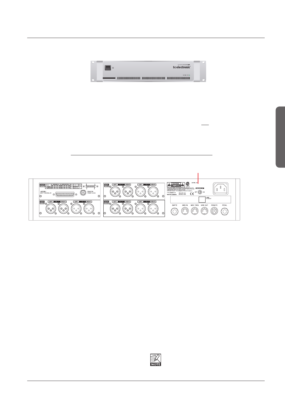
System 6000 Mainframe Rear
I/O Slot - A
I/O Slot - B (AES-8)
DSP Slot
I/O Slot - C
I/O Slots A, B and C
These slots are used for the optional I/O cards ADA 24/96
and AES-8. Slots must be filled consecutively in alphabetic
order.
The System 6000 DSP card fits in the DSP slot only. When
I/O cards are mounted, dip switches on the cards must be
set accordingly. Please see the following page.
An AES-8 card should be installed in “I/O Slot B (AES-8)”
only. If your mainframe rear panel carries a label saying
BUS updated you can install the AES-8 card yourself
following the instructions on the next of this chapter.
DSP Slot
The System 6000 DSP card is placed in the DSP Slot.
Power In
100-230V AC. 50/60Hz - auto-select.
LAN/Ethernet
Connection for external control devices e.g. the TC Icon.
The type is 32 bit PCI Ethernet interface fully compliant
with IEE 802.3u 10/100 Mbps CSMA/CD standards.
The connector type is a 100Base-T RJ-45 (CN13)
SMPTE
1/4” connection for SMPTE sync. Input.
Ground Lift
Use this standard chassis ground lift if you encounter
problems with hum.
MIDI In, Thru and Out
5 pin DIN connectors.
Remote
This connection is for service and test purposes only.
Pedal
General Purpose Input. Connect a TC Master Fader or a
tip to ground switch. Applications vary depending on the
specific algorithm.
Rack-mounting Advice
• The M6000 should not be placed in an environment with
a temperature exceeding 50 degrees Celsius.
• Do not cover the ventilation openings on the sides of the
frame.
The cooling fan is activated according to the
temperature inside.
Reset (countersunk)
Press and hold this button during boot to reset the frames
IP address to the default setting: 192.168.1.xx*, - where
“xx” is the last two digits in the frames serial number.
* Note - if the frames serial number ends on “00”, the IP
address will be: 192.168.1.100, as “00” is not a valid IP
number in all networks.
Serial Number