Page head, Page head clock and synchronization in system 6000 – TC Electronic Broadcast 6000 User Manual
Page 62
62
paGe Head
62
paGe Head
ClOCK and synCHrOnIzaTIOn In sysTem 6000
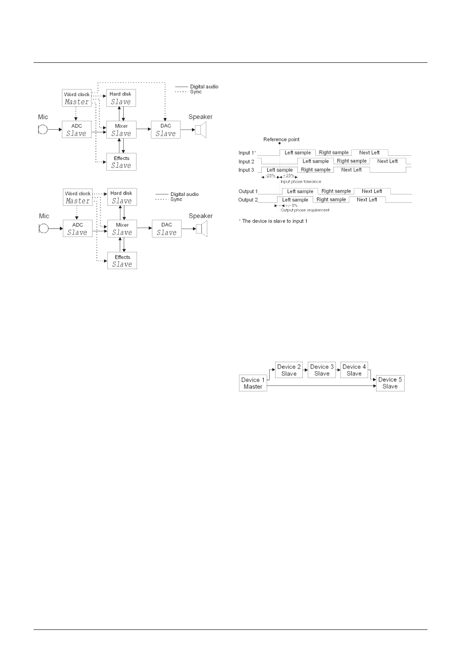
Figure 12 Same setup with a word clock generator.
Example with DAC with and without word clock input.
Figure 12 shows the example setup with a word clock
generator included. Some devices may not feature a word
clock input and these devices will then slave to the digital
signal carrying audio.
One of the advantages of using a word clock generator is
that there is no constant switching between master and
slave configurations. Just the normal patching signals
around through the patch bay.
Another advantage is that potential jitter accumulation is
reduced. The jitter sources from the clock master to where
AD- or DA-conversion is done are reduced to the word
clock generator intrinsic jitter, the word clock line to the
converting device and the intrinsic jitter in this device. For
setups with devices without word clock input the chain is a
bit longer.
A disadvantage of using a setup with word clock might
be that there will typically not be so much optimizing of
the jitter e.g. the ADC being master when recording and
the DAC being master when mixing. Even though the
clock path is short (from the word clock generator to the
converting device) having the converting device being the
clock master could optimize the setup further jitter wise.
Nominal phase.
Digital mixers with a lot of digital inputs and other
equipment e.g. surround devices have to be able to receive
signals from several sources at the same time.
In Figure 13 the timing of different input and output
signals is shown. AES specifies that a device must be
able to receive a signal with a phase of up to +/- 25% of
the sample period away from the reference. This means
that if the device is slave to input 1 the phase on the
other input signals must fall within +/- 25% of the sample
period away from the signal on input 1. If the phase of a
signal (including two audio channels) is above the limit,
the current sample in this signal can be interpreted as
the previous or the next sample and this will add a delay
to these specific two audio channels. A summing of the
signals later in the setup (e.g. electrically or acoustically)
will result in a potential audible phase error.
Figure 13 Nominal phase tolerances and requirements of
AES signals.
It is difficult to make equipment transmitting a digital signal
at exactly the same time as it receives a signal. Typically
a device will have both a delay of a whole number of
samples but also a sub sample delay. The delay of a whole
number of samples is due to the routing of the signal in
the device and the sub sample delay is due to the specific
hardware in the device. AES specifies that the output must
fall within +/- 5% of the sample period from the reference
point (the incoming signal if the device is in slave mode).
See Figure 13.
Figure 14 Example setup. Device 5 is slave to the signal
from device 1.
Consider a setup like Figure 14 where device 2 to 4 adds
a sub sample delay of 10% of the sample period. There
will now be a difference between the two signals going into
device 5 of 30% of a sample period. Now device 5 might
interpret the two inputs wrong the way mentioned above.
In a whole number of samples this might not be a problem
because device 2 to 4 also has perhaps 10 samples delay
pr. device equals a total delay of 30. So the resulting 1
sample extra delay in this chain due to several sub sample
delays might not matter.
Another problem might be that perhaps the jitter level after
device 4 is quite high. This jitter will perhaps make the
signal from device 4 continuously cross the point in device
5 where the signal is interpreted as the current sample or
the next. This will make continuous slip samples (perhaps
with audible clicks) on the input on device 5 receiving
signal from device 4.
A way to work around this could be to have device 3
slaving directly to device 1 with an extra synchronization
signal. This way the 10% sub sample delay in device 2
will be eliminated. A setup using word clock generator