Page head, Page head clock and synchronization in system 6000, Synchronization – TC Electronic Broadcast 6000 User Manual
Page 61
61
paGe Head
in dept
H
61
paGe Head
ClOCK and synCHrOnIzaTIOn In sysTem 6000
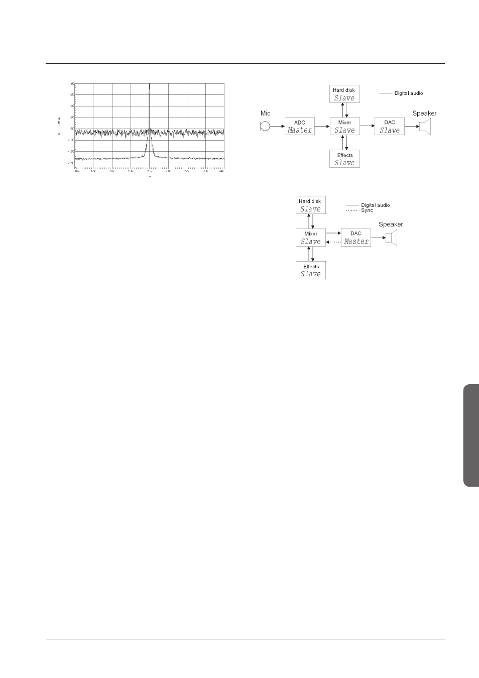
Figure 11 Digital studio setup with an ADC or DAC as
master.
• Digital signal (not carrying audio) e.g. AES11 or word
clock.
This way typically involves a device that makes
synchronization signals for the audio processing devices
in the setup.
This word clock generator is the master at all times and
all the audio devices are slaves.
The word clock is a square wave signal (typically TTL
level, 0 to 5V) with a frequency equal to the sample rate
e.g. 48kHz. The impedance is 75 ohm and the connector
is RCA phono or BNC.
The AES11 is an AES signal without audio and therefore
the connector is XLR with a 110 ohm impedance.
Figure 10 Zoomed (frq. only). System 6000 and
conventional design in slave-mode. Wide band jitter
applied.
On Figure 10 25 ns peak wide band jitter has been
applied to both System 6000 (lower) and a conventional
design (upper). The jitter level has formed a noise floor at
approx. -80 dB with reference to the 20 kHz tone on the
conventional design. The System 6000 curve reflects the
jitter rejection filter curve up to approx. 300 Hz (20 kHz +/-
300 Hz on this picture). Beyond 300 Hz the System 6000
has reduced the jitter so much that it is hidden in the noise
floor.
Synchronization
Synchronization: The digital signal, word clock or AES 11.
There are several ways to obtain synchronization in a
setup: Using a digital signal (carrying audio), a digital signal
(not carrying audio) or a word clock.
• Digital signal (carrying audio).
This is the simplest way to obtain sync and it involves
only the two (or more) audio devices that are connected.
Typically the transmitting device is the master and the
receiving device is the slave.
As mentioned earlier there is jitter to take into account
when selecting which device to be the master of timing.
Typically the internal clock in a device is the cleanest and
therefore when recording it is often the ADC that is the
master (see Figure 11). To get the best DA conversion
when mixing the DAC is often the master. But the DAC is
a receiver of the audio signal and therefore it is necessary
to send a synchronization signal from the DAC back to the
rest of the system. This can be done with a digital signal
that is or is not carrying audio and to which the system is
slave.