Page head clock and synchronization in system 6000, Measurements on system 6000 – TC Electronic Broadcast 6000 User Manual
Page 60
60
paGe Head
ClOCK and synCHrOnIzaTIOn In sysTem 6000
Measurements on System 6000
As mentioned before the higher frequency in the program
signal and the higher level the more sensitive it is to jitter
on the sampling clock. Therefore the measurements in
this document uses a 20 kHz sine at -1 dBFS and all
measurements are done at 48 kHz sample rate. The
measurements are done on the DA converter on the
ADA24/96 card and the test system is Audio Precision
System 2 Cascade.
To show the effect of the jitter being modulated via the
clock into the audio signal the measurements are FFT’s of
the analog signal on the ADA24/96 output.
Every full view picture is made with an FFT: 2k point, 256
times average, and equiripple window. Every frequency
zoomed picture is made with an FFT: 16k point, 32 times
average, and equiripple window.
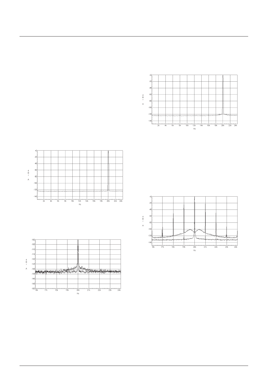
System 6000 performance
Figure 6 System 6000 DAC in master mode
The system is running in internal master mode thus there
is no jitter being applied to the system. Notice the very flat
noise floor with no spurious signals.
Figure 7 Zoomed version (both frq. and level) of Figure 6
plus System 6000 in slave mode.
On Figure 7 the system is running both internal master
mode (lower) and external slave mode (upper) where the
system is slave to the Cascade. There is no jitter being
applied from the Cascade so what is shown here is approx.
the difference in intrinsic jitter when the System 6000 is
slave to the digital input.
Notice that even with this much zoom the jitter on
internal-mode is not visible.
The very little jitter that shows on slave-mode is low
frequency weighted from 1kHz and down.
Figure 8 System 6000 DAC in slave mode, 1kHz jitter
applied.
Figure 8 is a full view picture when System 6000 is slave
and there is applied 1khz, 1.3us peak sine jitter. This is a
huge amount of jitter and actually beyond the tolerance
level specified by AES3-1992 amendment 1-1997 [3] that
all AES compatible devices should be able to lock to.
The performance of a conventional clock design
compared to the performance of the System 6000
Figure 9 Zoomed (frq. only) version of Figure 8 (lower) plus
the same level of jitter applied to a conventional design
(upper).
On Figure 9 the 1 kHz, 1.3 us peak sine jitter is applied to
System 6000 (lower) and a conventional design (upper)
without jitter rejection. Notice that the jitter spikes on the
conventional design reaches -22 dB with reference to the
20 kHz tone where the System 6000 has filtered out this
jitter by approx. 100 dB down to -122 dB.
There are more spikes than 20 kHz +/- 1 kHz. There are
also +/- 2, 3 and 4 kHz, which are harmonics on the sine
jitter generator. The low frequency noise floor on the upper
curve is probably noise in the jitter generator.