Page head, Installing additional i/o cards, I/o cards – TC Electronic Broadcast 6000 User Manual
Page 11: Ada 24/96 parameters
11
paGe Head
H
W
&
installation
11
InsTallInG addITIOnal I/O Cards
I/O Cards
I/O cards MUST be mounted in slots A, B and C
consecutively starting in slot A. Dip-switches must be
correctly set on the I/O cards.
To install an ADA 24/96 or AES-8 card in your Main
Frame 6000
1. Switch OFF the unit and disconnect the main
power cord.
2. Remove the DUM-1 option plate(s) or module by
loosening the 2 screws.
3. Insert the card gently and mount the two screws.
ADA 24/96 cards can be mounted in slots A, B or C.
The AES-8 card
must be placed in the AES slot.
Static Electricity
As all computer hardware can be sensitive to static
electricity, certain precautions must be taken to protect it
from damage during storage and handling.
Storage
Non-mounted modules should always be stored in
anti-static shielded bags.
General Handling
When inserting or removing any modules, avoid touching
the circuit board by handling only the rear panel of the
module. To minimize the static potentials that can cause
damage to the electronic circuits, you should observe
precautionary grounding techniques such as touching a
grounded System 6000 Mainframe immediately before
inserting modules.
Removing Modules
Before removing any card from your Mainframe, switch off
the power and unplug the main power cable. Unplug all
other connections from the module before unscrewing the
two screws securing the module in the Mainframe. When
removing a module from a Mainframe, the card should
be mounted directly in another Mainframe or placed in an
anti-static shielded bag.
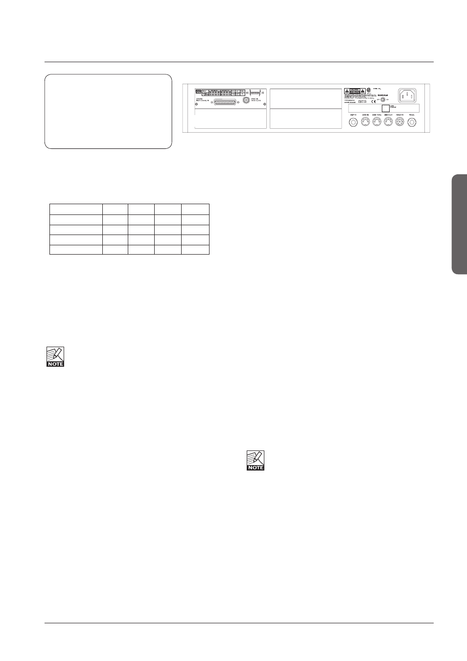
Slot A
Slot B / AES-8
Slot C
Dip 1 Dip 2 Dip 3 Dip 4
Slot
A
on off off off
Slot B
on
on
off
off
AES-8
off on off off
Slot
C
on off on off
Mounting Modules
Before mounting modules in your M6000, switch off the
power and unplug the main power cable. Remove the
dummy-panel or original module from the slot where you
want to install the module. The module should then be
removed from the shielded bag and mounted directly in the
Mainframe by handling the rear panel of the module only.
Avoid touching any components on the PCB-Board.
ADA 24/96 Parameters
To access card specific parameters via the TC Icon:
• Press
Frame, System, I/O and Slot A, Slot B or Slot C.
Level In
Changes the analog nominal Input level between +6dBu
and +30dBu in 6dB increments.
The analog Input level enables you to match the System
6000 Mainframe Input to the Output of e.g. your mixer. If
the nominal operating level your mixer is e.g. +4dBu and
you select +12dBu on the Level In parameter you will have
a headroom of 8dB. If you select +16dBu in the Analog In
the headroom will be +12dB, and so forth.
Level Out
Changes the analog Output level between +6dBu and
+24dBu in 6dB increments.
Filter
Select filter type. Chose between - Linear, Natural, Vintage,
Bright and Standard (Std). Further information on these
filters please read the chapter: In Depth Information.
These filters are only available in 44.1 and 48kHz.
Soft Clip
Softclip algorithm running in the 96kHz domain right after
the AD conversion before the down-sampling filter.
Output Connection
Please select the type of connection you are using on the
Output of the card. Select between:
Balanced or unbalanced (with signal on pin 2 or pin 3).
If you are connecting unbalanced cables to the
Outputs when Outmode set to BAL, the Outputs will be
muted due to the short circuit the unbalanced cables cause.
Caution!
The servicing instructions are for
use by qualified personnel only. To
reduce the risk of electric shock do
not perform any servicing other than
that in the operation instructions
unless you are qualified to do so.