Grain Systems Bucket Elevtors, Conveyors, Series II Sweeps PNEG-1204 User Manual
Page 55
Proper mounting has been achieved when the
scribed line on the locknut has rotated from the
scribed line on the adapter face by the angle shown
on Table 1. To reach the full rotation of the locknut,
the use of hammer blows onto spanner or drift may
be needed for proper mounting. In high vibration or
impact loading applications, maximum nut rotation is
required.
Table 1
Locknut Angle of Rotation From
“Zero Reference Point”
SHAFT
BASIC
LOCKNUT ROTATION
SIZE
BRG. NO.
DEGREES
TURNS
1
1
/
8 -
1
1
/
2
22208K
235 +/– 25
5
/
8
to
3
/
4
turns
1
5
/
8 -
1
3
/
4
22209K
285 +/– 25
3
/
4
to
7
/
8
turns
1
7
/
8 -
2
22210K
285 +/– 25
3
/
4
to
7
/
8
turns
2
3
/
16 -
2
1
/
4
22211K
360 +/– 40
7
/
8
to 1
1
/
8
turns
2
3
/
8 -
2
1
/
2
22213K
360 +/– 40
7
/
8
to 1
1
/
8
turns
2
11
/
16 -
3
22215K
360 +/– 40
7
/
8
to 1
1
/
8
turns
3
3
/
16 -
3
1
/
2
22218K
450 +/– 40
1
1
/
8
to 1
3
/
8
turns
3
11
/
16 -
4
22220K
450 +/– 40
1
1
/
8
to 1
3
/
8
turns
4
7
/
16 -
4
1
/
2
22222K
405 +/– 40
1 to 1
1
/
4
turns
4
15
/
16 -
5
22226K
495 +/– 40
1
1
/
4
to 1
1
/
2
turns
5
7
/
16 -
5
1
/
2
22228K
495 +/– 40
1
1
/
4
to 1
1
/
2
turns
5
15
/
16 -
6
22232K
360 +/– 40
7
/
8
to 1
1
/
8
turns
6
7
/
16 -
7
22236K
405 +/– 40
1 to 1
1
/
4
turns
5. a) Slide lockplate over shaft and align tang of lock-
plate with slot in adapter sleeve.
b) Find a locknut hole that aligns with a lockplate
hole. If the closest locknut hole is beyond a lock-
plate hole, then tighten, not loosen, the locknut
to meet a lockplate hole.
c) Insert lockwasher and tighten button head screws
to lock assembly. (Ref. Picture 4)
The turning of the locknut must start from a “zero
reference point.” This “zero reference point” is
defined as the point when the clearance between
adapter sleeve, shaft and bearing bore has been
removed, and all surfaces are in metal to metal con-
tact. To reach the “zero reference point,” rotate lock-
nut clockwise, using both hands, as tight as possible.
From this point use a spanner or drift and hammer
and rotate the locknut an additional
1
/
8
of a turn. This
is your “zero reference point.” This all needs to be
done with weight off bearing.
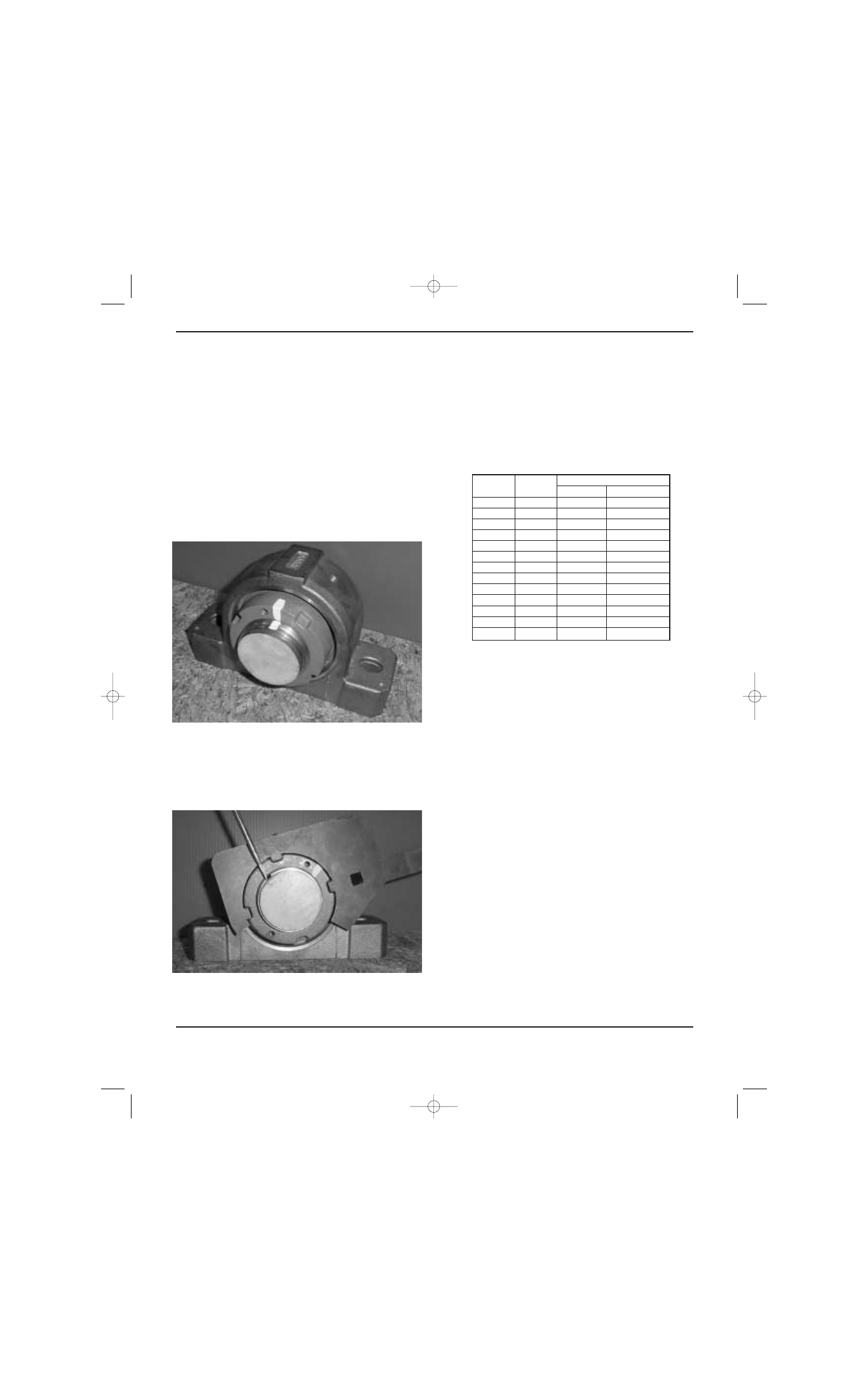
Picture 2
Picture 3
4. Once “zero reference point” is reached, scribe a line
through both locknut face and adapter face
(Picture 2).
Then continue to tighten the locknut (Picture 3) by
turning it clockwise using hammer and drift or span-
ner by the appropriate rotation angle shown on
Table 1.
6. Bolt down pillow block or flange unit to the structure.
7. Repeat steps 1 through 6 for the expansion bearing
except immediately after Step 2 do the following:
6954 Layout 3/1/02 8:50 AM Page 2
48 PNEG-1204 Enclosed Belt Conveyors
48 PNEG-1204 Enclosed Belt Conveyors
50 PNEG-1204 Enclosed Belt Conveyors