Torque-arm ii bushing installation – Grain Systems Bucket Elevtors, Conveyors, Series II Sweeps PNEG-1204 User Manual
Page 44
CAUTION: Unit is shipped without oil. Add proper amount of
recommended lubricant before operating. Failure to observe
this precaution could result in damage to or destruction of the
equipment
8. Fill gear reducer with recommended lubricant. See Table 2.
KEEP
CLOSE
KEEP
CLOSE
INPUT
SHAFT
DRIVEN
SHAFT
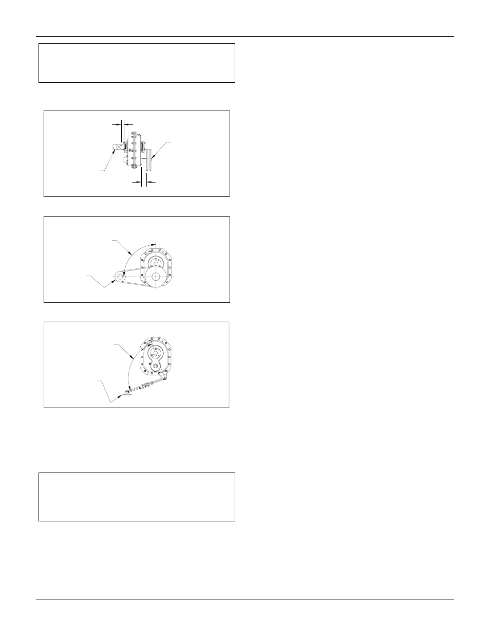
Figure 2 – Reducer and Sheave Installation
RIGHT ANGLE OR
MAY VARY 30°
V-BELT
DRIVE
V-BELT
DRIVE MAY
BE LOCATED
TO THE
RIGHT IF
DESIRED
Figure 3 – Angle of V-Drive
TORQUE
ARM MAY
BE LOCATED
TO THE
RIGHT IF
DESIRED
RIGHT ANGLE OR
MAY VARY 20° IN
TENSION OR
COMPRESSION
TORQUE-ARM
AND BELT
TAKE-UP
Figure 4 – Angle of Torque-Arm
TORQUE-ARM II BUSHING
INSTALLATION
WARNING: To ensure that drive is not unexpectedly started,
turn off and lock out or tag power source before proceeding.
Remove all external loads from drive before removing or
servicing drive or accessories. Failure to observe these
precautions could result in bodily injury.
The Dodge Torque-Arm II Reducer is designed to fit both
standard and short length driven shafts. The Standard Taper
Bushings series is designed where shaft length is not a concern.
The Short Shaft Bushing series is to be used where the driven
shaft does not extend through the reducer.
Standard Taper Bushings:
1. One bushing assembly is required to mount the reducer on
the driven shaft. An assembly consists of two tapered bushings,
bushing screws and washers, two bushing backup plates and
retaining rings, and necessary shaft key or keys. The driven
shaft must extend through the full length of the reducer. If the
driven shaft does not extend through the reducer do not use the
standard tapered bushings; instead use the short shaft bushings
as described in the Short Shaft Bushings section that follows.
The minimum shaft length, as measured from the end of the
shaft to the outer edge of the bushing flange (see Figure 5), is
given in Table 1.
2. Install one bushing backup plate on the end of the hub and
secure with the supplied retaining ring. Repeat procedure for
other side.
3. Place one bushing, flange end first, onto the driven shaft and
position per dimension “A”, as shown in Table 1. This will allow
the bolts to be threaded into the bushing for future bushing and
reducer removal.
4. Insert the output key in the shaft and bushing. For easy of
installation, rotate the driven shaft so that the shaft keyseat is at
the top position.
5. Mount the reducer on the driven shaft and align the shaft key
with the reducer hub keyway. Maintain the recommended
minimum distance “A” from the shaft bearing.
6. Insert the screws, with washers installed, in the unthreaded
holes in the bushing flange and align with the threaded holes in
the bushing backup plate. If necessary, rotate the bushing
backup plate to align with the bushing screws. Tighten the
screws lightly. If the reducer must be positioned closer than
dimension “A”, place the screws with washers installed, in the
unthreaded holes in the bushing before positioning reducer
making sure to maintain at least 1/8” between the screw heads
and the bearing.
7. Place the second tapered bushing in position on the shaft
and align the bushing keyway with the shaft key. Align the
unthreaded holes in the bushing with the threaded holes in the
bushing backup plate. If necessary, rotate the bushing backup
plate to align with the bushing holes. Insert bushing screws, with
washers installed in the unthreaded holes in the bushing.
Tighten screws lightly.
8. Alternately and evenly tighten the screws in the bushing
nearest the equipment to the recommended torque given in
Table 1. Repeat procedure on outer bushing.
Short Shaft Bushings:
1. One bushing assembly is required to mount the reducer on
the driven shaft. An assembly consists of one long tapered
bushing, one short tapered bushing, one tapered bushing
wedge, bushing screws and washers, two bushing backup
39
PNEG-1204 Enclosed Belt Conveyors