Options motion sensor option – Grain Systems Bucket Elevtors, Conveyors, Series II Sweeps PNEG-1204 User Manual
Page 38
33
PNEG-1204 Enclosed Belt Conveyors
Options
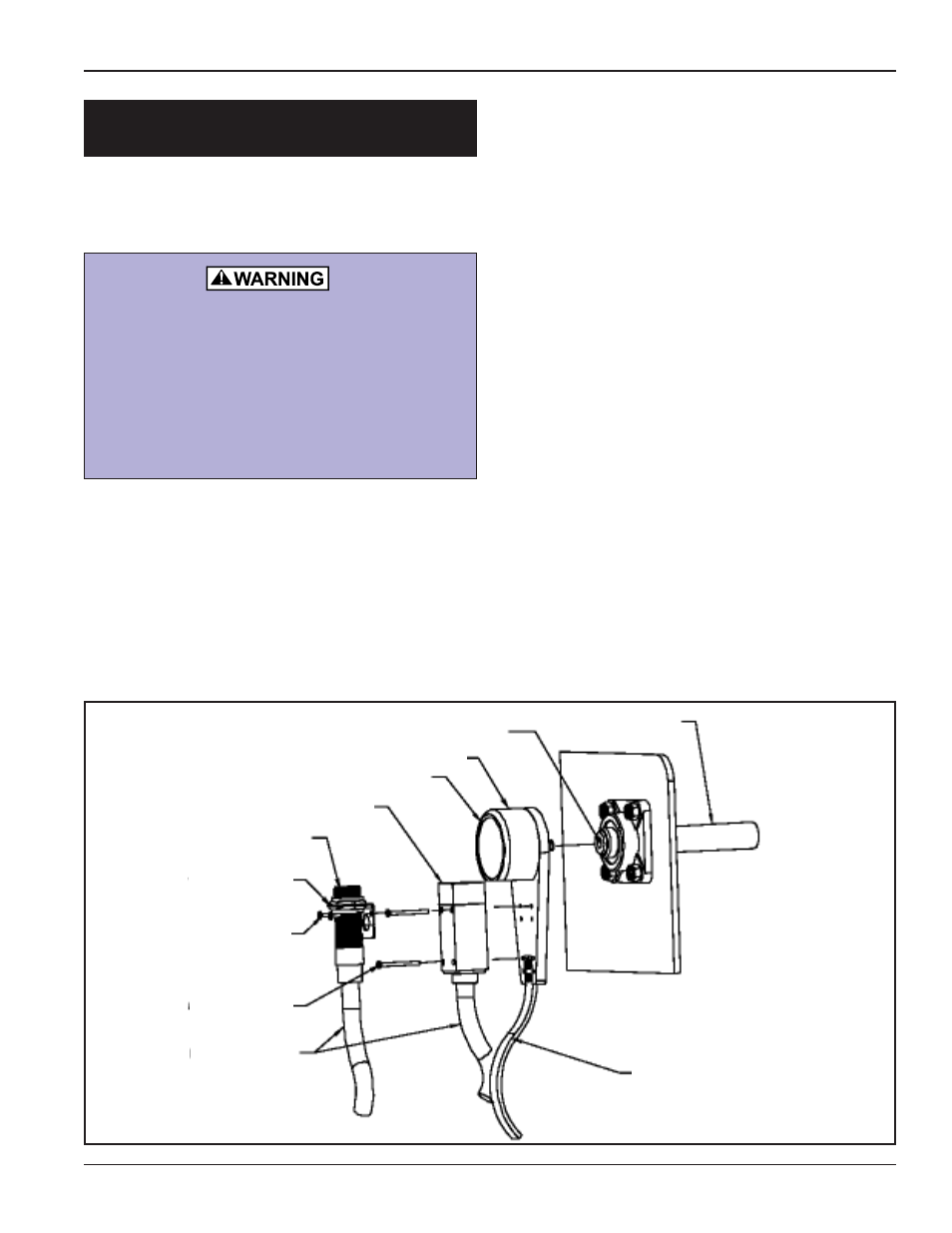
MOTION SENSOR OPTION
1. Shaft ends are predrilled and tapped from
the factory.
2. Thread the WHIRLIGIG onto the machine
shaft using 5/8" open ended wrench and
suitable thread locking adhesive (Loctite or
similar).
3. Install the sensor to the WHIRLIGIG base-
plate. Two sets of predrilled holes are pro-
vided for M800 sensor. Fit the sensor to
leave an approximate 2mm gap between
sensor face and cover.
A universal bracket (WGB18/30) is supplied
for fitting 18mm or 30mm sensors.
4. Connect the sensor in accordance with
manufacturer’s instructions and observe all
relevant electrical & OSHA regulations.
5. Fix the flexible strap securely to the static
structure. (If required).
TIP: The M800 speedswitch and system
function can be tested by placing a thin
metal plate between the sensor and the
cover of the WHIRLIGIG. When installing
other industry standard sensors, leave a
small gap between the sensor & the
WHIRLIGIG cover for this purpose.
WHIRLIGIG - WG1-4B
Installation Instructions
ALWAYS OBSERVE LOCKOUT AND TAG-
OUT PROCEDURES BEFORE, DURING
AND AFTER INSTALLATION.
DO NOT REMOVE THE WHIRLIGIG
COVER. THE ROTATING COMPONENTS
UNDER THE COVER COULD CAUSE
SERIOUS INJURY.
Monitored Shaft
Tap Shaft for 1/2" UNC Centered
Cover
The Whirligig
M800 Sensor
Cylindrical Sensor
18/30mm Bracket
(Supplied)
10mm Screws (4)
(Supplied)
50mm Screws (4)
(Supplied)
Flexible Conduit
Flexible Strap