Backstops – Grain Systems Bucket Elevtors, Conveyors, Series II Sweeps PNEG-1204 User Manual
Page 52
BACKSTOPS
WARNING:
To ensure that drive is not unexpectedly started,
turn off and lock out or tag power source before proceeding.
Remove all external loads from drive before removing or
servicing drive or accessories. Failure to observe these
precautions could result in bodily injury.
1.
Remove backstop shaft cover and gasket, shown in Figure 7.
These parts will not be reused. This cover is directly opposite
the extended end of the input shaft.
2.
Clean the face of the gearbox to remove any gasket material
or contamination from the cover mounting surface. It is
important that contamination not get into the gearbox or the
backstop during the backstop installation/servicing process.
3.
Face reducer looking at the side from which the cover was
removed. Determine carefully the desired direction of free
rotation. It is important that the direction be correctly
determined because to reverse the direction after the backstop
is installed, it is necessary to remove the backstop, turn it end-
for-end and then reinstall it.
4.
Match the arrow on the backstop inner race to the direction
of free rotation for the desired shaft. Note that reversing the
backstop end-for end changes the direction of the arrow. The
shaft will rotate in the same direction as the arrow on the
backstop.
5.
If the backstop kit has a spacer ring included, install it onto
the shaft first, adjacent to the bearing inner ring.
6.
Install the backstop inner race and sprag cage assembly
onto the shaft. DO NOT remove the cage from the inner race or
the shipping strap from the sprag set at this time. Insert the key
into the inner race and mating shaft keyway. These parts
should slip onto the shaft easily, a light coating of oil may assist
in assembly. Do not use a hammer to force the installation,
damage can occur to the shaft and/or the backstop. Slide the
race against the spacer or the shaft shoulder and install the
retaining ring into the groove in the shaft. Only use the supplied
key, as it is specifically designed for each backstop.
7.
Apply a thin coating of RTV silicone onto the gearbox mating
surface for the outer race (same as the cover area). It is
important to apply the sealant around the fastener holes to
prevent leakage. Do not allow excessive amounts of silicone to
enter the gearbox or to be applied to other parts.
8.
Install the outer race by gently rotating it opposite the shaft
rotation while pressing lightly inwards. Do not force the outer
race into position as backstop damage may occur. Once the
outer race is well piloted onto the sprag set, remove the
shipping strap from the sprag set by cutting it, being careful not
to let the outer race back off the sprags. The outer race should
slide easily into position with a slight turning motion. A light
coating of oil on the race inner diameter may ease installation.
9.
Align the fastener holes in the outer race with the mating
holes in the gearbox. Use the supplied grade 5 fasteners and
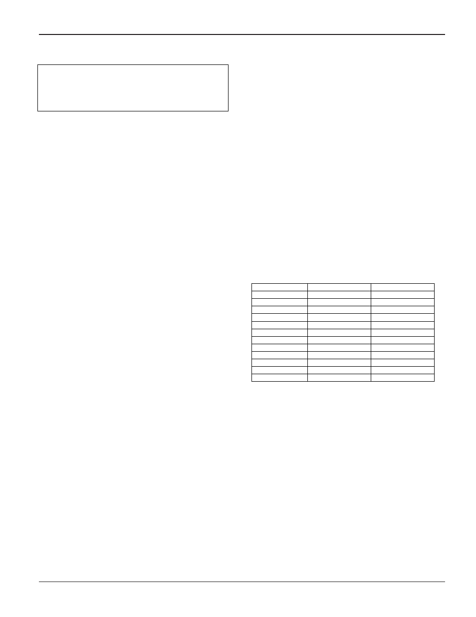
lock washers only. Torque the fasteners in an alternating
pattern per Table 5.
Table 5 – Backstop Fastener Torque Values
Reducer Size
Fastener Size
Torque in Ft.-Lbs.
TA0107L
1/4-20
8 – 7
TA1107H
1/4-20
8 – 7
TA2115H
1/4-20
8 – 7
TA3203H
1/4-20
8 – 7
TA4207H
1/4-20
8 – 7
TA5215H
5/16-18
17 – 15
TA6307H
5/16-18
17 – 15
TA7315H
3/8-16
30 – 27
TA8407H
5/16-18
17 – 15
TA9415H
3/8-16
30 – 27
TA10507H
3/8-16
30 – 27
TA12608H
3/8-16
30 – 27
47
PNEG-1204 Enclosed Belt Conveyors