V-Tech DT-IP Technical Guide User Manual
Page 24
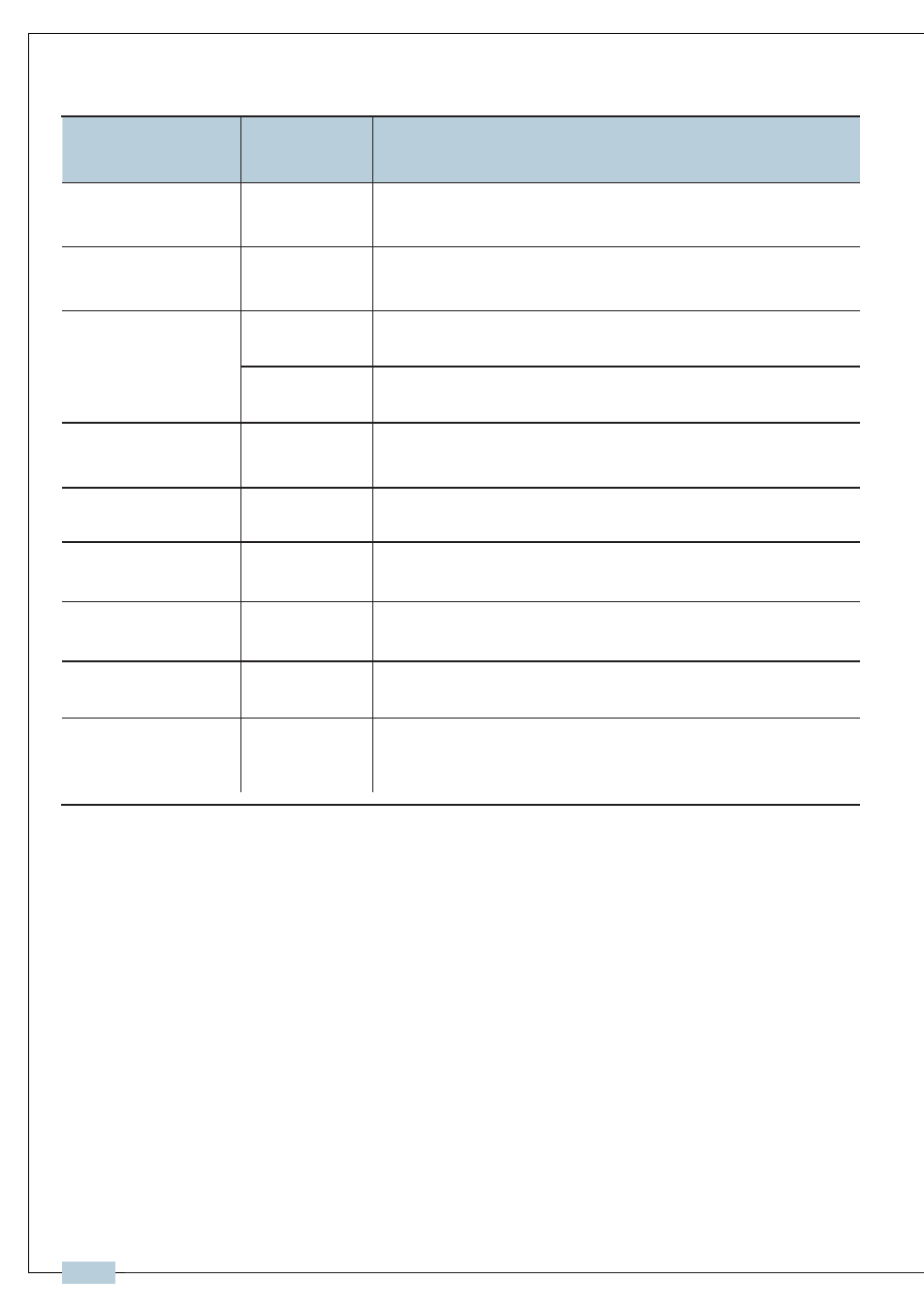
Terminal description:
Item
Name
Description
Status indicator
LED202
After power on for 10s,it will flicker
Always on while working
LED203
DIP switches
SW201
Refer to DIP switches setting in followings
S201
Refer to DIP switches setting in followings
Network Signal Input
J701
RJ45 connection, connected to network.
Bus Signal Output
CN-BSO
2 wire terminal connection,to DT-DPS connection
Bus signal input
CN-BS1
2 wire terminal connection, to monitors or DBC4s
that monitors are connected
Bus signal input
CN-DS
Connected to door station or DBC4s that door
stations are connected
Prog Button
K201
Reserved
PC port
RS485
Set parameters of DT-IPC by PC that is connected
by RS485-USB Convertor
Power input: DC 24Vdc (supplied by DT-DPS)
Standby Current: 190 mA
Working Current: 250mA
Video Signal: CCIR, 1Vp-p , 75Ω
Audio Signal: 300~3,400 KHz, 0~240 mV
Transmission Mode: TCP/IP
Connection Port: RJ45
Network Interface: Standard Ethernet interface
Working temperature: +5ºC ~ +40ºC
Dimension: 140(W)X60(H)X150(D)mm
2.2.3 Specification
-23-
IP-2 wire system technical guide