Veris Industries SDI SERIES Install User Manual
Page 7
66
7
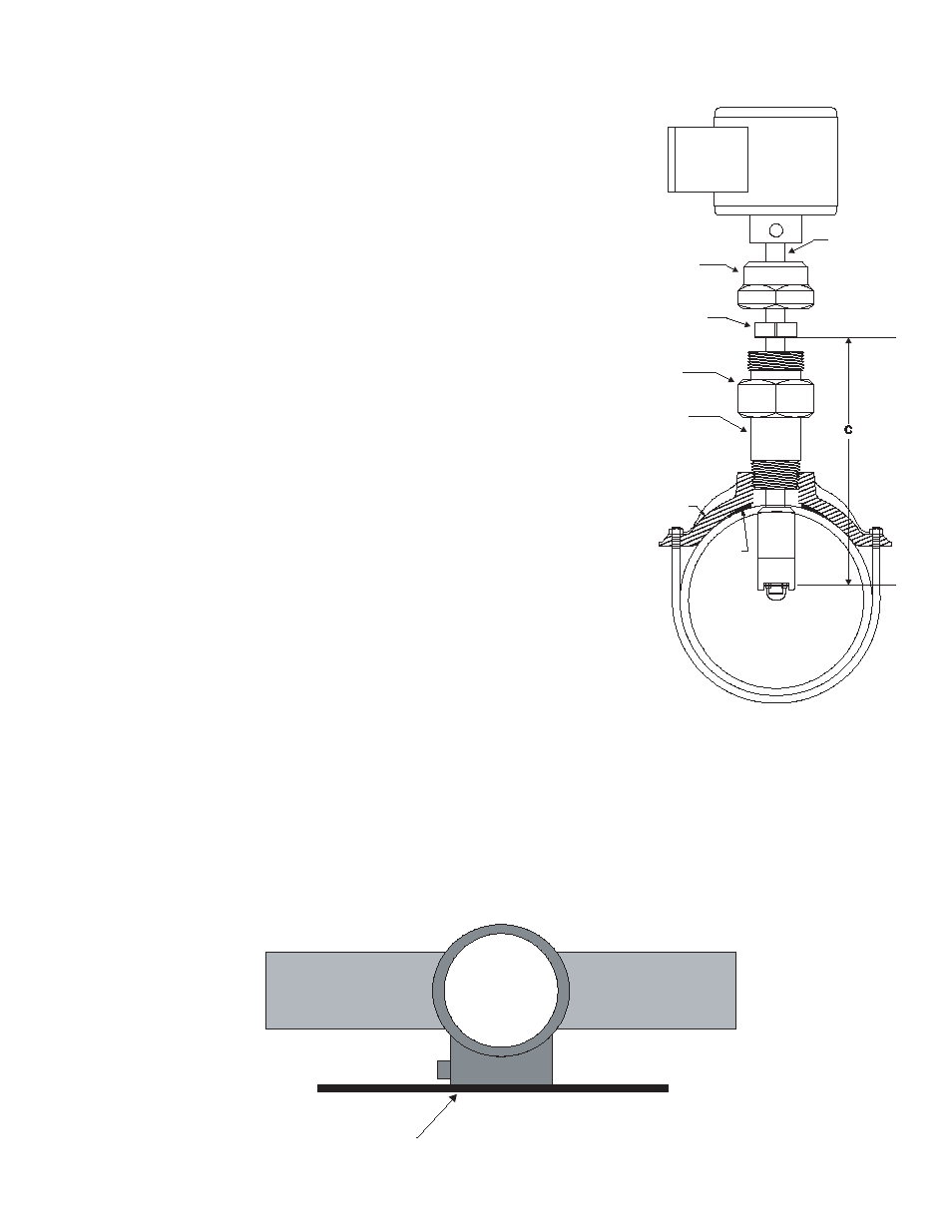
Pipe Saddle
(ref.)
Mounting
Adapter
Gasket
(ref)
Stem
Stem Collar
Hex Cap
Cover
1. Attach the saddle to a section of pipe that has at least 10 diameters
of straight pipe ahead and five diameters of straight pipe behind the
saddle. Drill a minimum 1 1/8” diameter hole in the pipe.
2. Remove the sensor assembly from the mounting hardware by loosening
the hex cap over the stem collar and the cover to the mounting adapter
and detaching the assembly. Set aside taking care not to damage im-
peller/shaft assembly.
3. Attach the pipe thread end of the mounting adapter to the saddle/weld-
o-let using a pipe joint compound and tighten the joint. Do not apply
sealing compound to the top thread of the mounting adapter. It is sealed
with an o-ring.
4. The sensor rotor assembly is to be located a fixed distance from the
center of the pipe. To position the impeller at this depth, a reference
measurement for the pipe size and schedule is used. Look up the pipe
size and schedule number in
Table A and note the reference number.
Next, measure from the outside wall of the pipe to the top of the installed
mounting adapter “B” in Figure 3. Add this number to the reference mea-
surement.
The resulting number, “C” in Figure 4 is the distance from the recess of
the sensor tip to the bottom of the stem collar. Insert the metal tab of
a tape measure into the recess of the flow sensor tip. Extend the tape
up the stem and mark the shaft with a pencil. Slide the collar along the
shaft until its bottom surface is at the mark on the stem. Tighten the cap
screw on the collar. When the sensor is reassembled, this will set the
insertion depth of the sensor.
5. Attach the sensor to the mounting adapter by gently pushing the flow
sensor into the mounting adapter until the cover touches the mounting
adapter. Tighten the cover against the o-ring seal. This will seal the
sensor assembly.
6. Continue to insert the flow sensor stem until the stem collar meets the cover. Thread the hex cap onto the mount-
ing adapter but don’t tighten. Align the flow sensor with the pipe by using the flat cover on the electronics hous-
ing as a guide. Place a straightedge along the cover and rotate the sensor until the straightedge is parallel with
the pipe. Tighten the hex cap over the collar approximately 10 foot pounds. The hex cap holds the sensor align-
ment but performs no sealing functions. DO NOT OVERTIGHTEN.
7. Pressurize pipeline and check for leaks.
Straight Edge Parallel to Pipe
Pipe
Pipe
SDI
Flow Sensor