Veris Industries SDI SERIES Install User Manual
Page 11
10
10
11
Electrical Installation
Access wiring terminals by removing side cover. A wiring diagram is on the side cover, under the gasket. Use care
when replacing side cover to insure that the gasket is in place.
DO NOT REMOVE CIRCULAR COVER from top of sensor. You may disturb seal and label alignment.
A moisture absorbing silica pack has been placed inside the electronics housing during assembly. Leave in place after
making wire connections.
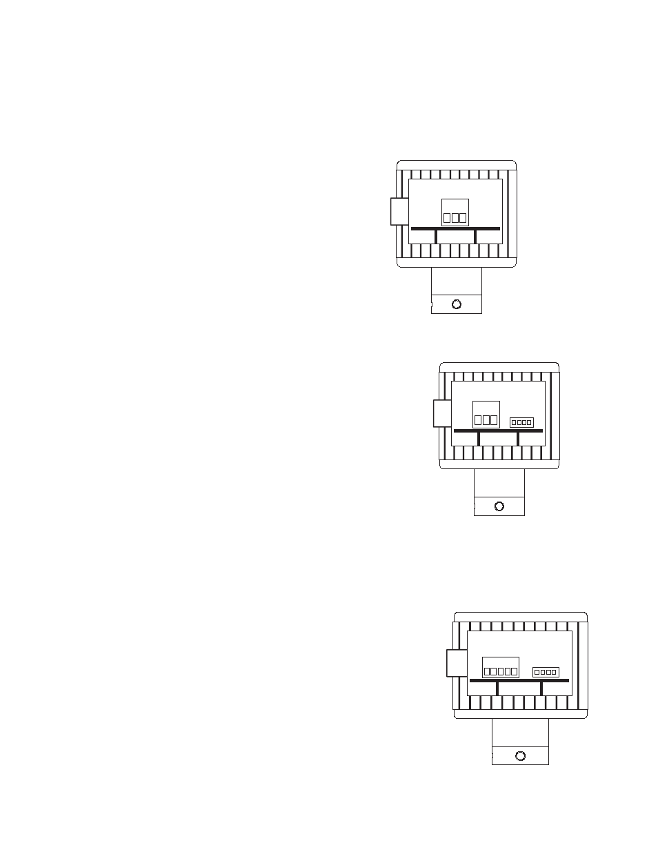
Standard frequency (Pulse) output - Option “0” in the
ordering matrix
This two wire sensor is intended for connection to Data Industrial
monitors and transmitters or other devices that supply 10-24 DC
excitation voltage and accept frequencies from 0 to 1000Hz.
Attach the sensor shield terminal 1 to the shield terminal on the
transmitter (used for maximum protection from interference).
Attach the sensor common terminal 2 to the common (-) terminal
on the transmitter.
Attach the sensor signal terminal 3 to the signal (+) terminal on the
transmitter.
Analog 4-20mA Output - Option “1” in the ordering matrix
This option provides a programmable 4-20 mA signal proportional to flow
rate. All programming is accomplished as previously mentioned. The user
can program the unit for pipe size, flow scale. This is a two-wire option.
Attach
SDI #1 (Shield) to Earth Ground or Power Supply Common. (This
provides maximum power and signal EMI protection).
ANALOG OUTPUT – WIRED AS CURRENT SINKING
Attach
SDI#2 (Loop -) to the Analog input terminal of device receiving this
4-20mA signal.
Attach
SDI#3 (Loop +) to +24VDC terminal of device receiving the 4-20mA
Signal.
ANALOG OUTPUT – WIRED AS CURRENT SOURCING – (WITH SEPA-
RATE 24VDC POWER SUPPLY)
Attach
SDI#2 (Loop -) to Analog input terminal of device receiving this
4-20mA signal. (Sometimes labeled Loop
+).
Attach
SDI#3 (Loop +) to +24VDC Supply terminal.
Attach -24VDC Supply terminal to the Analog Input Common. (Sometimes labeled Loop
-).
Scaled Pulse output - Option “2” in the ordering matrix
This option provides a programmable opto-isolated solid state switch closure
with internal solid state fuse protection. All programming is accomplished as
previously mentioned. The user can program the unit for pipe size, flow scale
and the direction of flow. This is a six-wire option.
Attach
SDI #1 (Shield) to Earth Ground or Power Supply Common. (This
provides maximum power and signal EMI protection).
Attach
SDI #2 (Power -) to the negative terminal of a nominal
12-24VAC/VDC Power Supply. (See data sheet for current draw and voltage
limits).
Attach
SDI#3 (Power +) to positive terminal of power supply.
Attach
SDI #4 (Pulse -) to the Input pulse (-) of the receiving device.
Attach
SDI #5 (Pulse +) to the Input pulse (+) of the receiving device.
1. Shield
2. Power -
3. Power +
4. Pulse -
5. Pulse +
1 2 3 4 5
1 2 3
1. Shield
2. Loop -
3. Loop +
1 2 3
1. Shield
2. Sensor Common
3. Sensor Signal