Single direction analog output models – Veris Industries SDI SERIES Install User Manual
Page 14
14
14
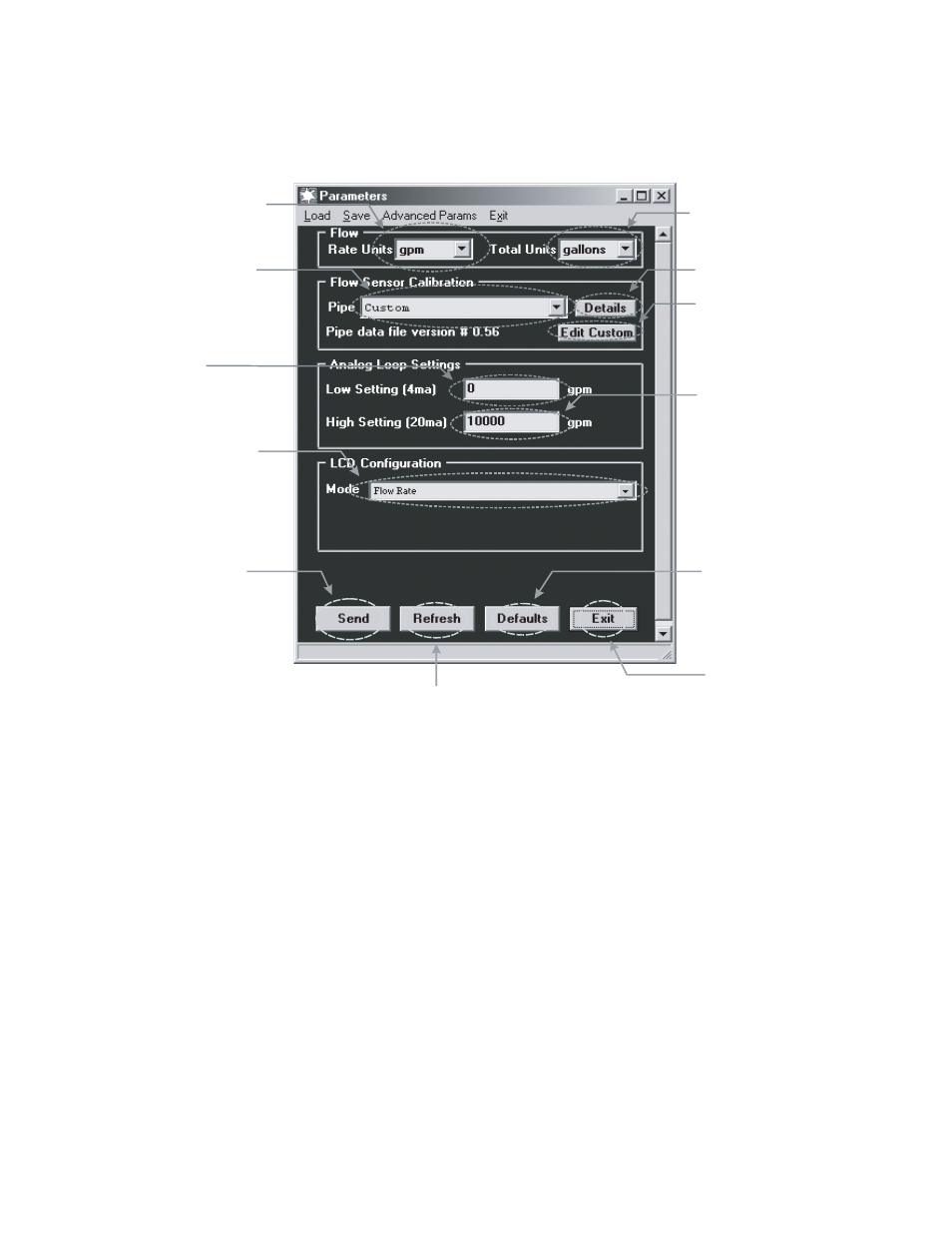
6. Program using diagram below as a reference.
Note #1
Press “details” to see “K” and “offset” numbers for the selected pipe. The “K” and “offset” are
factors used to convert the sensor frequency to flow rate. They are unique to each pipe size/
material.
Note #2
Press “custom” button to enter “K” and “offset” numbers for pipe material not listed in pull down
menu. The numbers may be obtained by contacting Data Industrial.
Single Direction Analog Output Models
Step #1
Select rate units from the pull down
values.
Step #2
Select total units from the
pull down values.
Step #3
Select the pipe size from the pull
down menu, if the pipe size is not
present then custom must be
selected, or check for an updated
pipe.dat table on the Data Industrial
web site.
See Note #1
Step #4
Note #2.
If custom was selected in step 3
then click the custom button
and see
Step #5
Enter 4mA flow rate. This is
normally zero.
Step#6
Enter 20mA flow rate.
Step #7
Step #8.
For models with LCD Display Option
select the desired LCD Configuration
from the pull down menu. If Model
has no display then skip to
Step #8
Press Send to transmit calibration
data to the SDI Sensor.
Press to retrieve calibration
data from SDI.
Press to reset all parameters
back to factory defaults. Send
must be pressed to send this
data to the SDI.
Step #9
Press to exit parameters
screen and to go back to the
main screen.