Veris Industries SDI SERIES Install User Manual
Page 12
12
12
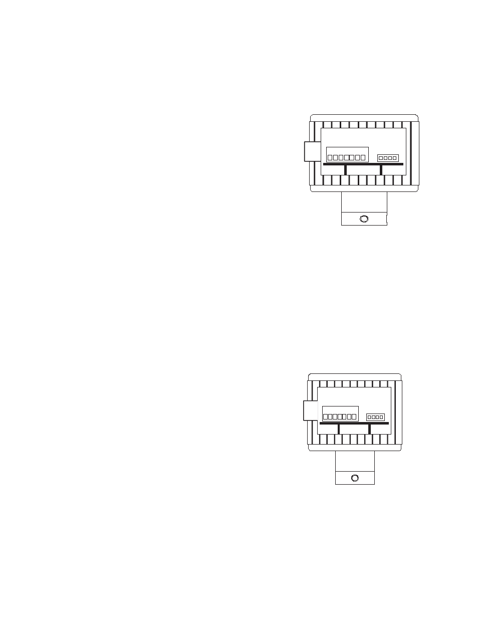
Bi-Directional Analog Output - Option “5” in the ordering matrix
This option provides a programmable 4-20 mA signal proportional to flow rate and a contact closure to indicate the
direction of flow. All programming is accomplished as previously mentioned. The user can program the unit for pipe
size, flow scale and the direction of flow. This is a six-wire option.
Attach
SDI #1 (Shield) to Earth Ground or Power Supply Common. (This provides maximum power and signal EMI
protection).
Attach
SDI #2 (Power -) to the negative terminal of a nominal
12-24VAC/VDC Power Supply. (See data sheet for current draw and voltage
limits).
Attach
SDI#3 (Power +) to positive terminal of power supply.
Attach
SDI #4 and SDI#5 (Direction +/-) to the device receiving the direc-
tional signal. (This connection is not polarity sensitive; and, when active,
provides a solid state switch closure for a maximum load of 100mA @30VAC
or +/-40VDC).
ANALOG OUTPUT – WIRED AS CURRENT SINKING
Attach
SDI#6 (Loop -) to the Analog input terminal of device receiving this
4-20mA signal.
Attach
SDI#7 (Loop +) to +24VDC terminal of device receiving the 4-20mA
Signal.
ANALOG OUTPUT – WIRED AS CURRENT SOURCING – SHARING SDI’s 24VDC POWER SUPPLY
Attach
SDI#6 (Loop -) to Analog input terminal of device receiving this 4-20mA signal.
Attach
SDI#7 (Loop +) to SDI#3. (Sharing terminal with +24VDC Supply).
Attach
SDI#2 (Loop -) to Analog Input Common. (Sometimes labeled Loop -).
ANALOG OUTPUT – WIRED AS CURRENT SOURCING – (WITH SEPARATE 24VDC POWER SUPPLY)
Attach
SDI#6 (Loop -) to Analog input terminal of device receiving this 4-20mA signal. (Sometimes labeled Loop +).
Attach
SDI#7 (Loop +) to +24VDC Supply terminal.
Attach -24VDC Supply terminal to the Analog Input Common. (Sometimes labeled Loop
-).
Bi-Directional Scaled Pulse Output - Option “6” in the ordering matrix
This option provides a programmable scaled pulse output signal proportional to flow rate and a contact closure to
indicate the direction of flow. All programming is accomplished as previously mentioned. The user can program
the unit for pipe size, flow scale and the direction of flow. This is a six-wire
option.
Attach
SDI #1 (Shield) to Earth Ground or Power Supply Common. (This
provides maximum power and signal EMI protection).
Attach
SDI #2 (Power -) to the negative terminal of a nominal
12-24VAC/VDC Power Supply. (See data sheet for current draw and voltage
limits).
Attach
SDI#3 (Power +) to positive terminal of power supply.
Attach
SDI #4 (Pulse B -) to the Input pulse (-) of the receiving device.
Attach
SDI #5 (Pulse B +) to the Input pulse (+) of the receiving device.
Attach
SDI #6 (Pulse A -) to the Input pulse (-) of the receiving device.
Attach
SDI #7 (Pulse A +) to the Input pulse (+) of the receiving device.
1. Shield
2. Power -
3. Power +
4. Direction
5. Direction
6. Loop -
7. Loop +
1 2 3 4 5 6 7
1. Shield
2. Power -
3. Power +
4. Pulse B -
5. Pulse B +
6. Pulse A -
7. Pulse A +
1 2 3 4 5 6 7