Veris Industries SDI SERIES Install User Manual
Page 10
10
10
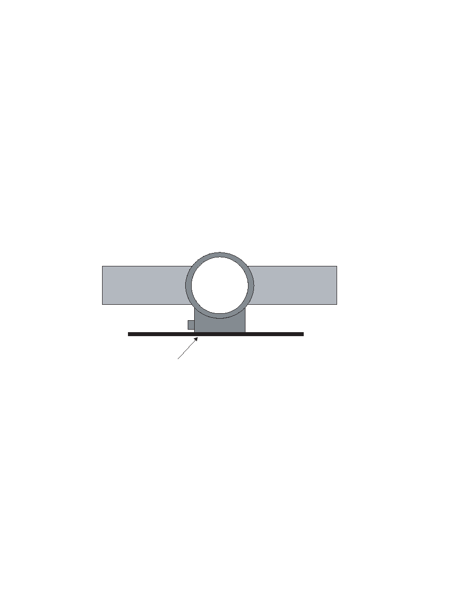
Straight Edge Parallel to Pipe
Pipe
Pipe
SDI
Flow Sensor
10. Slide the cover down the stem until it stops. Attach the sensor to the valve by inserting the impeller end of the
stem into the valve until the cover touches the top of the valve. The sensor tip and impeller will be in the section
of the valve above the ball. Tighten the cover against the o-ring in the top of the valve. This will seal the sensor
assembly. Open the ball valve again by slowly rotating the handle 90° If the cover was not at the bottom of the
sensor stem, water pressure from the pipe would now push it out until it stops. However, the sensor cannot be
ejected from the pipe if the cover is secured to the valve. Check to make sure all joints are tight.
11. Insert the flow sensor stem into the pipe by pushing against the top of the electronics housing with a slight
twisting motion until the stem collar meets the cover. The force required to push the sensor into the pipeline is
approximately 20% of the line pressure. Be aware of the close spacing between the diameter of the flow sensor,
the bore of the ball valve and the hole in the pipe. If the sensor stops or “catches” before the stem collar meets
the cover, apply a gentle rocking/twisting motion to the sensor to continue its travel. While holding the flow sensor
collar against the cover, thread the hex cap onto the cover to hold the flow sensor in place but do not tighten.
Align the flow sensor with the pipe by using the flat side cover of the electronics housing as a guide. Place a
straightedge along the cover and rotate the sensor until the straightedge is parallel to the pipe. Tighten the
hex cap to the cover to approximately 10 foot pounds. The hex cap holds the sensor alignment and depth but
performs no sealing functions. DO NOT OVERTIGHTEN.
12. Pressurize pipeline and check for leaks.