Installation guide, Communications unit modbus point map, Ea10 series – Veris Industries EA10 SERIES Install User Manual
Page 7
ZL0102-0A
PAGE 7
©2012 Veris Industries USA 800.354.8556 or +1.503.598.4564 / [email protected]
05126
Alta Labs, Enercept, Enspector, Hawkeye, Trustat, Veris, and the Veris ‘V’ logo are trademarks or registered trademarks of Veris Industries, L.L.C. in the USA and/or other countries.
TM
INSTALLATION GUIDE
EA10 SERIES
COMMUNICATIONS UNIT MODBUS POINT MAP
The EA10 supports the SunSpec Common Model and Basic String Combiner maps. See www.sunspec.org for more information. A proprietary Veris point map (encoded in the
SunSpec style) follows with configuration and status information not provided in SunSpec. The layout of these register blocks is as follows:
Register Block
Start
End
SunSpec Common Model
40001
40069
SunSpec Basic String Monitor – up to 32 channels
40070
40343
Veris Proprietary Status & Configuration
40344
40416
SunSpec Null Block
40417
40418
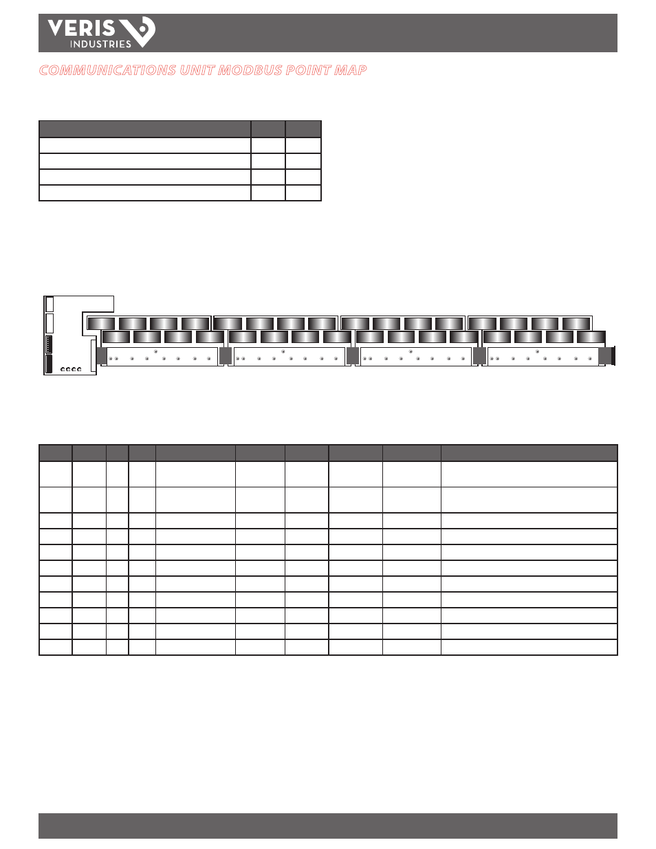
Current Sensing Module Mapping
When using multiple current sensing modules (up to 4 per communications unit), map the location of each individual current sensor. The table and diagram below show how
each sensor is numbered. The current sensing module closest to the communications unit is module 1 and utilizes strings (channels) 1 through 8 (see the illustration below).
1
3
5
7
2
4
6
8
9
11
13
15
10
12
14
16
17
19
21
23
18
20
22
24
25
27
29
31
26
28
30
32
Communications
Unit
Current Sensing Module
1
Current Sensing Module
2
Current Sensing Module
3
Current Sensing Module
4
Common Modbus Model Point Map
Modbus maps are defined using this common table format. Register addresses are absolute using base 1 notation. This table has been modified from the original SunSpec
relative addressing format to absolute addressing.
Start
End
#
R/W
SunSpec Name
Type
Units
Scale Factor
Contents
Description
40001
40002
2
R
C_SunSpec_ID
uint32
N/A
N/A
0x53756e53
(SunS)
Well-known value. Uniquely identifies this as a SunSpec
Modbus map
40003
40003
1
R
C_SunSpec_DID
uint16
N/A
N/A
0x0001
Well-known value. Uniquely identifies this as a SunSpec
Common Model block
40004
40004
1
R
C_SunSpec_Length
uint16
registers
N/A
65
Length of common model block
40005
40020
16
R
C_Manufacturer
String(32)
N/A
N/A
N/A
“Veris Industries”
40021
40036
16
R
C_Model
String(32)
N/A
N/A
N/A
“EA10HC1AB”
40037
40044
8
R
C_Options
String(16)
N/A
N/A
N/A
“Basic”
40045
40052
8
R
C_Version
String(16)
N/A)
N/A
N/A
Product version
40053
40068
16
R
C_SerialNumber
String(32)
N/A
N/A
N/A
Product serial number
40069
40069
1
R/W
C_DeviceAddress
uint16
N/A
N/A
N/A
Modbus ID
40070
40070
1
R
C_SunSpec_DID
uint16
N/A
N/A
Device ID
Start of next device
40071
40071
1
R
C_SunSpec_Length
unit16
N/A
N/A
Device Length
Device model block size
Basic String Combiner Modbus Register Map
The Basic String Combiner Modbus mapping allows a variable number of strings (8, 16, 24, or 32). The Veris implementation is fixed at 32 strings for ease of integration
with existing Modbus master devices. As current sensing modules are added, the data from each CT appears, starting in the first block. The CT closest to the
communications unit is identified as String 1, and so on. Any int16 values that are not supported return 0x8000. This table has been modified from the original SunSpec
relative addressing format to absolute addressing. Combiner level readings provide combined values for current, amp-hours, voltage, status, and events. Individual string
readings are provided for the current and events.