Installation guide, Ea10 series – Veris Industries EA10 SERIES Install User Manual
Page 4
ZL0102-0A
PAGE 4
©2012 Veris Industries USA 800.354.8556 or +1.503.598.4564 / [email protected]
05126
Alta Labs, Enercept, Enspector, Hawkeye, Trustat, Veris, and the Veris ‘V’ logo are trademarks or registered trademarks of Veris Industries, L.L.C. in the USA and/or other countries.
TM
INSTALLATION GUIDE
EA10 SERIES
• The terminal’s voltage and current ratings are compliant with the
requirements of the EIA RS-485 communications standard.
• The RS-485 transceivers are ¼ unit load or less.
• RS-485+ has a 47 kΩ pull up to +5V, and RS-485- has a 47 kΩ pull down
to Shield (RS-485 signal ground).
• Wire the RS-485 bus as a daisy chain from device to device, without
any stubs. Use 120 Ω termination resistors at each end of the bus (not
included).
• Shield is not internally connected to earth ground.
• Connect Shield to earth ground somewhere on the RS-485 bus.
For all terminals on EA10 devices:
• When tightening
terminals, apply the
correct torque: 0.37-
0.44 ft·lb (0.5-0.6 N·m).
• Use 12-24 gauge wire.
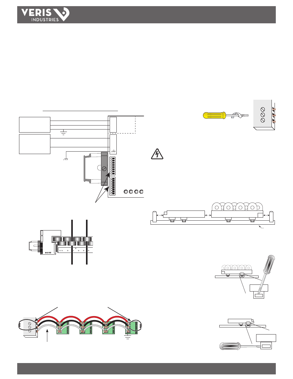
To Remove Sensing Modules and Communications Unit From DIN Rail
Disconnect and lock out power to panel or combiner box,
including power to all strings.
1. Unplug the RS-485 and control power connectors from the communications unit.
Disconnect strings and remove them from the current sensing module(s).
2. Loosen or remove the DIN stop clips. Separate the EA10 components by sliding
them apart along the DIN rail. Ensure that the current sensing modules are fully
disconnected from adjacent modules and from the communications unit.
DIN Rail
3. If there is sufficient space on one end of the DIN rail, continue sliding each
component along the rail until they slide off one end.
4. If space is limited, and step 3 is not
possible, then insert a screwdriver into
the groove on the DIN rail clips on one
side of a current sensing module. Use
the screwdriver to pry the clip away
from the DIN rail. Repeat with the
second clip on the same module. The
current sensing module lifts off of the
DIN rail when both clips are loosened.
5. Repeat with any other current sensing modules on the rail.
6. To remove the communications unit, turn
the screwdriver so that it is parallel to the
DIN rail and insert it between the clip and
the DIN rail. Pry the clip away from the DIN
rail. Repeat with the second clip on the
unit. The communications unit lifts off the
DIN rail when both clips are loosened.
9. Configure communications unit using DIP switches (see page 5 to set the DIP
Switches).
10. Wire RS-485 communications to communications unit using the 3-pin connector
provided.
11. Wire 24 to 42 VDC control power to the communications unit using the 4-pin
connector provided.
Caution: Do not apply control power to the 3-pin RS-485 connector.
12. Wire the communications unit to the enclosure’s chassis ground using the 4-pin
connector. Ensure that the enclosure’s chassis ground is tied to earth ground.
Wiring for RS-485 and Control Power Connectors
Modbus
Master
RS-485
+
–
S
+
–
S
24 VDC
Power
Supply
+
–
+
–
RS-485
(isolated)
DC Power
Sta
tus
Tx
Rx/E
rror
Po
we
r
20-P
in C
onnec
tor
DIP switches
13. Route each insulated conductor through a DC current sensor.
14. Restore power to the panel and commission the device for operation.
Connecting Multiple Communications Units in a Daisy Chain
The RS-485 slave port allows connection of multiple EA10 communications units in a
daisy chain with up to 63 2-wire devices.
–
+
S
120 Ω terminator on the first and
last device of the daisy chain
Shield wire
Red
Black
Gray
0.37–0.44 ft•lb
(0.5–0.6 N•m)
Use 14-24 gauge wire