Installation guide, Installation – Veris Industries EA10 SERIES Install User Manual
Page 3
ZL0102-0A
PAGE 3
©2012 Veris Industries USA 800.354.8556 or +1.503.598.4564 / [email protected]
05126
Alta Labs, Enercept, Enspector, Hawkeye, Trustat, Veris, and the Veris ‘V’ logo are trademarks or registered trademarks of Veris Industries, L.L.C. in the USA and/or other countries.
TM
INSTALLATION GUIDE
EA10 SERIES
INSTALLATION
Disconnect and lock out power to panel or combiner box,
including power to all strings.
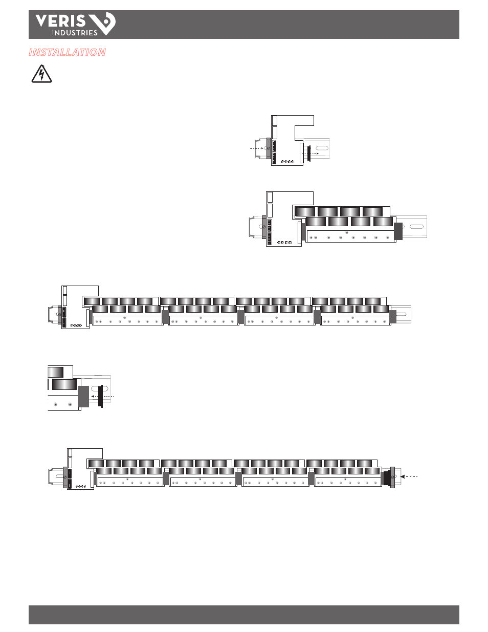
1. Select a location in a panel, adjacent to the fuse block to be monitored.
2. Install and tighten a DIN rail stop clip (included) near the end of the 35 mm DIN
rail (sold separately) in the panel or combiner box. Apply the correct torque to the
stop clip screw: 0.37 to 0.59 ft-lb (0.5 to 0.8 N·m).
3. Mount the communications unit onto the DIN rail and slide it up against the stop
clip.
4. Remove the end cap from the communications unit 20-pin connector. Retain for
later use.
5. Mount DC current sensing module(s) onto the DIN rail. Connect the first current
sensing module to the communications unit via the 20-pin connector plug.
Confirm that the o-ring is installed in the plug to ensure a tight fit.
Note: Disconnect power to panel and strings before connecting or
disconnecting current sensing modules.
6. Connect up to three additional current sensing modules, as needed, to produce
one continuous string of up to four modules per communications unit. For each
module, confirm that the o-ring is installed in the plug.
7. Place the end cap on the open 20-pin connector on the last DC current sensing
module. Confirm that the o-ring is installed in the end cap to ensure a tight fit.
8. Install and tighten the second DIN stop clip (included) to the end of of the
assembled EA10 DC String Monitoring System to prevent movement over time.