Installation guide, Dip switch settings – Veris Industries EA10 SERIES Install User Manual
Page 5
ZL0102-0A
PAGE 5
©2012 Veris Industries USA 800.354.8556 or +1.503.598.4564 / [email protected]
05126
Alta Labs, Enercept, Enspector, Hawkeye, Trustat, Veris, and the Veris ‘V’ logo are trademarks or registered trademarks of Veris Industries, L.L.C. in the USA and/or other countries.
TM
INSTALLATION GUIDE
EA10 SERIES
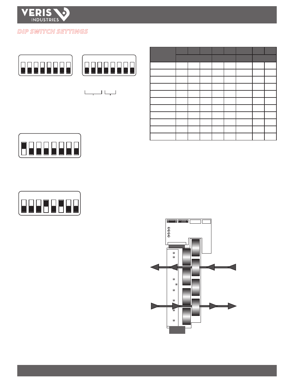
DIP SWITCH SETTINGS
The communications unit serial interface can be configured for Modbus address, baud
rate, and parity. No other configuration is supported.
On
Off
On
Off
LSB
MSB
Address
Baud
Parity
1 2 3 4 5 6 7 8
1 2 3 4 5 6 7 8
Unused
Unused
Rev
erse
Even/O
dd
On/O
ff
128
64
32
16
8
4
2
1
How to Set Address DIP Switches
Each DIP switch has a numerical value as shown below. The EA10 default address is 1,
as illustrated below.
On
Off
1 2 3 4 5 6 7 8
1 2 4 8 16 32 64 128
(DIP Switch Values)
To determine an address, add the values of any switch that is in the ON position.
For example:
1 2 3 4 5 6 7 8
On
Off
1 2 4 8 16 32 64 128
(DIP Switch Values)
Switches 4 and 6 are in the ON position, with values of 8 and 32, respectively.
8 + 32 = 40, so the EA10 address is 40.
Communications and Parity DIP Switches
Switch
Function
1
2
3
4
5
6
7
8
Baud
Parity
Reverse
Not Used
1200 Baud
OFF
OFF
OFF
X
X
2400
ON
OFF
OFF
X
X
4800
OFF
ON
OFF
X
X
9600
ON
ON
OFF
X
X
19200
OFF
OFF
ON
X
X
38400
ON
OFF
ON
X
X
No Parity
OFF
X
X
X
Odd Parity
ON
OFF
X
X
Even Parity
ON
ON
X
X
Current Flow
OFF
X
X
Current Flow
ON
X
X
Reverse Current Switch
The reverse current switch allows the user to define the polarity of the instantaneous
current reported by the unit. In the default Off position, the unit reports positive
current when the conductor is routed through the CT with current flowing towards
the DC current sensing module LEDs (see drawing below). Negative current flows
away from LEDs towards the CT, indicating a diagnostic event. When the reverse
current switch is On, the opposite is true (see drawing below). This feature allows the
product to be installed in a variety of configurations.
The state of the reverse current switch can be overridden by writing to the
configuration register via Modbus (see EA10 Modbus Point Map, System Configuration
Register 40357). To reactivate the switch, clear the Modbus register.
Reverse Off,
Unit reports positive current
Reverse On,
Unit reports positive current