Ohaus AS Series Electronic Balances User Manual
Page 74
5
5.
Remove the cover.
6.
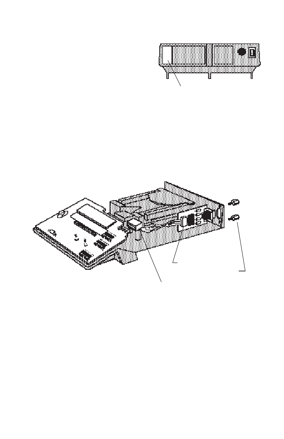
On the rear of the balance, a protec-
tive thin plate covers the hole for the
9-pin RS232 connector.
Peel off the plate to expose the hole.
7.
Place the circuit board and connector
assembly in the balance so that the 9-
pin connector fits through the hole.
Remove Plate
8.
Fasten the assembly using the two
screws provided.
9.
Slide the ribbon connector onto the
edge connector of the main circuit
board.
10. Replace the cover and fasten the
three screws that were removed.
11. Replace the draft shield.
12. Replace the pan and pan support.
13. Reconnect power to the balance.
Ribbon
Connector
RS232
Circuit
Board
Fasten
Screws
See also other documents in the category Ohaus Scales:
- MB45 MOISTURE ANALYZER Manual (70 pages)
- PRIMER BALANCE Manual (16 pages)
- DEFENDER 5000 BENCH SCALES Cable Adapter Kit Manual multi (2 pages)
- CARAT PLUS PRECISION JEWELRY BALANCES 2nd RS232 Serial Interface Kit Manual multi (24 pages)
- DEFENDER 5000 Semi-Washdown Scales Data Sheet (4 pages)
- SCOUT PRO PORTABLE BALANCES Data Sheet (4 pages)
- JR Series Electronic Balances (32 pages)
- EB COMPACT SCALES Data Sheet (2 pages)
- E1M110 Explorer Balances (47 pages)
- CKW WASHDOWN CHECKWEIGHING SCALES_INDICATOR Manual en (68 pages)
- RANGER COUNT 3000 COMPACT COUNTING SCALES Data Sheet (4 pages)
- RANGER ADVANCED COMPACT COUNTING SCALES Manual en (72 pages)
- Valor 2000 COMPACT FOOD SCALES Data Sheet (4 pages)
- DEFENDER D500M MECHANICAL BENCH SCALE Data Sheet (2 pages)
- CKW BASE Manual multi (40 pages)
- Valor 3000 COMPACT FOOD SCALES Manual multi (104 pages)
- Valor 1000 COMPACT FOOD SCALES Data Sheet (2 pages)
- PAJ GOLD PLUS PRECISION JEWELRY BALANCES Data Sheet (4 pages)
- Voyager Balances (329 pages)
- SD COMPACT BENCH SCALES Data Sheet (2 pages)
- CL PORTABLE BALANCES Manual multi (44 pages)
- CL PORTABLE BALANCES Data Sheet (2 pages)
- HH 120D HAND HELD SCALES Manual multi (40 pages)
- CD-11 Indicator Manual multi (120 pages)
- CARAT PLUS PRECISION JEWELRY BALANCES Manual en (56 pages)
- SCOUT PRO PORTABLE BALANCES Installation it (2 pages)
- DEFENDER 7000 BENCH SCALES Base Manual (2 pages)
- GT4100DG Electronic Balances (52 pages)
- FD Series STAINLESS STEEL COMPACT SCALES Manual multi (88 pages)
- PL150 Scale Bases (10 pages)
- DEFENDER 3000 BENCH SCALES Base Manual en (8 pages)
- DEFENDER 3000 Xtreme Data Sheet (2 pages)
- HJ2001 HARVARD JUNIOR MECHANICAL BALANCE Data Sheet (2 pages)
- VN Series Floor Scale Data Sheet (4 pages)
- DS Series Electronic Digital Bench Scales (38 pages)
- YA GOLD HAND HELD JEWELRY SCALES Data Sheet (2 pages)
- DEFENDER 7000XW Xtreme Square Washdown Scales Data Sheet (4 pages)
- DEFENDER 7000 Square Semi-Washdown Scales Data Sheet (4 pages)
- PS POCKET JEWELRY SCALES Data Sheet (2 pages)
- RANGER COMPACT HIGH RESOLUTION SCALES Data Sheet (2 pages)
- CARAT & GOLD LIGHT PORTABLE JEWELRY BALANCES Manual multi (88 pages)
- 311 CENT-O-GRAM BALANCE Manual (8 pages)
- DEFENDER 5000 Rectangular Scales Data Sheet (4 pages)
- MB301 Electronic Balances (29 pages)