M&C TechGroup SP180-H Operator's manual User Manual
Page 12
12
Gas sampling and gas conditioning technology
2.7a-ME
After mounting of the probe at the sampling flange put the heat insulating protection cover
over the probe flange again and secure it with the metal clamp .
N O T E !
A preferred mounting position is to have the probe with its sample gas outlet
pointing downwards, although this is not absolutely necessary for perfect
functioning.
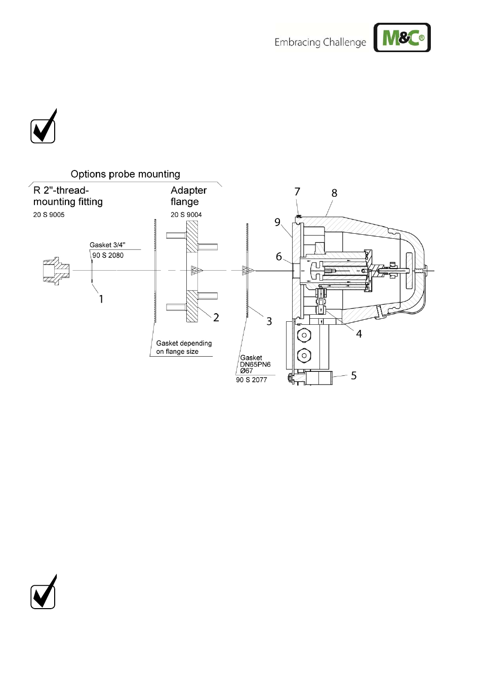
Figure 2
Mounting of the SP180-H
13.1 CONNECTION OF THE HEATED SAMPLE LINE
In order to connect the sample line, a threaded tube connector for dimension Ø 6x1mm is
available – other dimensions on request.
Open
metal
clamp
.
Introduce the tube connection piece into the bolted pipe joint and connect.
If a PTFE tube is used as sample line, a carrying bracket must under all circumstances be
inserted in the end of the tube in order to prevent the tube being pressed together.
The temperature-resistant, stainless steel connector supplied by M&C has a double-blade
ring system to ensure reliable sealing. After tightening the nut of these connector by hand, it
should then be tightened exactly 1¼ of a turn using a flat spanner and are then properly
mounted.
Put the heated sample line to the open metal clamp and close it.
N O T E !
Make sure that the connection is leakproof !