Figure 5, Electrical connections – M&C TechGroup EC-L Series Operator's manual User Manual
Page 13
13
Gas sampling and gas conditioning technology
3-3.1-ME
N O T E !
Attention must be paid to the requirements of IEC 364 (DIN VDE
0100) when setting high-power electrical units with nominal
voltages of up to 1000V, together with the associated standards
and stipulations.
An external main switch must be provided.
The main circuit must be equipped with a fuse of 10AT
(over
current protection); for electrical details see technical data (8.).
W A R N I N G !
Cooler versions with 115V resp. 120V have a built-in transformer
to generate an internal current of 230V. That means, device internal
live parts have a current of 230V not 115V/120V.
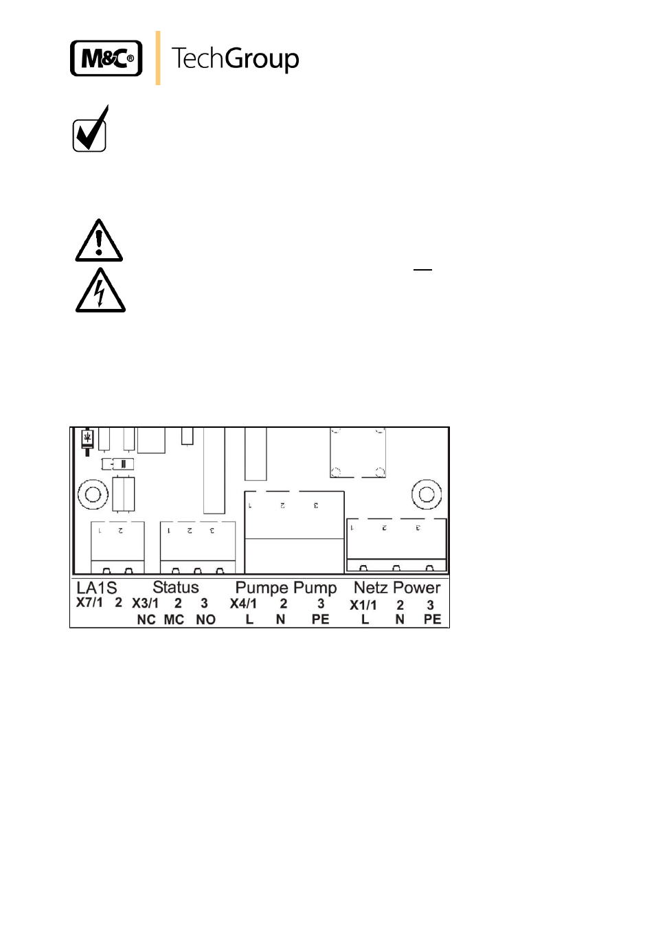
Figure 5 shows the electrical connections behind the front panel of the EC-L housing (fig. 2).
Alarms for excess- and low-temperature and liquid alarm (if connected) are given as a collective status
alarm via a relay output with a potential-free changeover contact. Alarm will be released if the current
temperature is out of a range of ±3°C referring to the set-temperature (+5°C) or if the liquid sensor
gets wet. A sample pump connected to terminal X4 will be switched off via an internal relay in case of
liquid alarm.
Figure 5 Electrical connections
The connection of the mains respectively , liquid alarm sensor, pump and status alarm signals
happens as follows:
release the captive screws (6 pcs.) at the cooler front and then swing open the front plate;
put the cables (6-12mm) through the cable glands M20 and connect them with the provided
plugs according to above mentioned wiring plan;
if a liquid alarm should be connected put the cable of the liquid alarm sensor through the cable
gland M12 and connect it with the provided plug according to above mentioned wiring plan;
the re-installation happens in the opposite way.