Installation instructions, Supply connections, Hose connections – M&C TechGroup EC-L Series Operator's manual User Manual
Page 11: Figure 4
11
Gas sampling and gas conditioning technology
3-3.1-ME
12
INSTALLATION INSTRUCTIONS
The EC-L cooler is suitable for wall mounting.
N O T E !
The operating position for this cooler is exclusively vertical. This is the
only way to ensure proper separation and removal of condensate in the
heat exchangers. During transport and installation, the cooler must
always be stood up with the transport feet positioned underneath so that
the oil in the closed compressor circuit cannot run out of the compressor
case.
The cooler should be kept away from sources of heat and well ventilated
when installed, so that condensation from warmth will not occur and
interfere with operation.
The minimum installation dimensions (fig. 2) must be followed without
fail. If the unit is installed in the open, the cooler must be installed in a
housing that is frost-free in winter and adequately ventilated in summer.
Avoid locating the unit in direct sunlight.
Unheated gas sample lines must be provided with slope up to the cooler.
In that case pre-separation of the condensate is not required. Connect the
heated sample line with sufficient thermal decoupling of min. 20cm to the
cooler!
13
SUPPLY CONNECTIONS
13.1
HOSE CONNECTIONS
The connection for sample gas inlet and outlet happens on the upper part of the heat exchangers. For
possible connectors see technical data (8.).
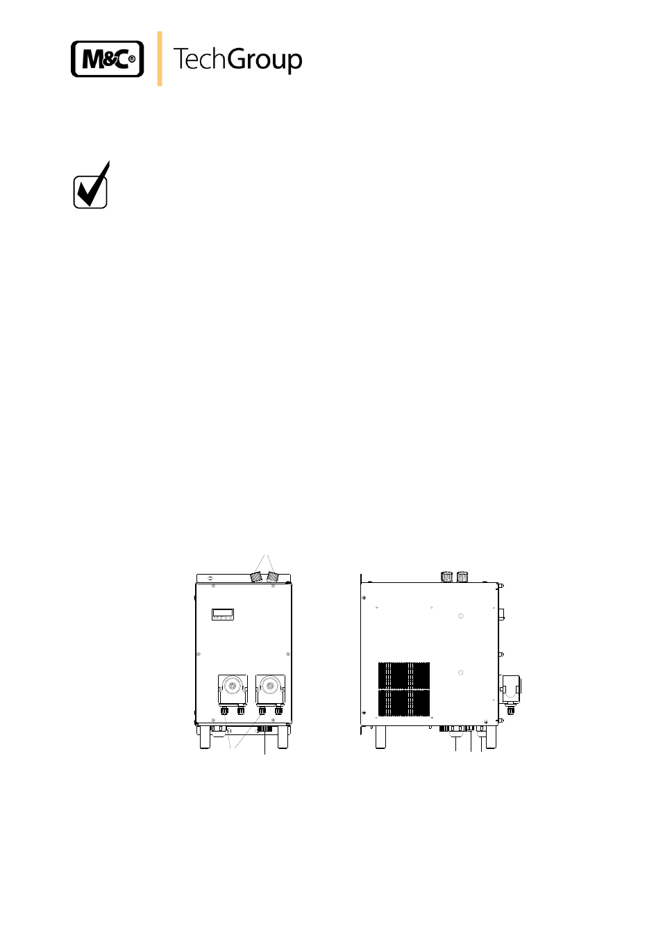
Figure 4 Position of the gas and condensate connections and the cable glands
4
5
1
2
3
4
1 Gas in- and outlet
2 Condensate outlet
3 Condensate outlet with incorporated peristaltic pumps
4 Cable glands M20 x 1,5
5 Cable gland M12 x 1,5