1 eis display, Engine indication system – Garmin G1000 Mooney M20TN User Manual
Page 86
Garmin G1000 Pilot’s Guide for the Mooney M20M/M20R/M20TN
190-00647-02 Rev. A
72
ENGINE INDICATION SYSTEM
SY
STEM
O
VER
VIEW
FLIGHT
INSTRUMENTS
EIS
AUDIO P
ANEL
& CNS
FLIGHT
MANA
GEMENT
HAZARD
AV
OID
ANCE
AFCS
ADDITIONAL FEA
TURES
APPENDICES
INDEX
3.1 EIS DISPLAY
1
Engine Manifold Pressure
Gauge (MAN IN)
Displays manifold pressure in inches of Mercury (in Hg) to indicate
engine power.
Turbocharged Aircraft – Maximum manifold pressure range shown in red
2
Tachometer (RPM)
Displays propeller speed in revolutions per minute (rpm); the red band
indicates propeller overspeed
3
Fuel Quantity Indicator
(FUEL QTY GAL)
Displays the amount of fuel in gallons (gal) for each tank (L and R)
Standard Tanks – Indicator displays up to 44.5 gallons when full
Long Range Tanks (options) – Allows 50 gallons per side (100 gallons total),
51 gallons per side (102 gallons total), or 65 gallons per side (130
gallons total), although the indicator range is the same as for standard
tanks. The pointers show tanks as full until the fuel quantity decreases
below 44.5 gallons.
4
Fuel Pressure Indicator
(FUEL PSI)
Displays the fuel pressure in pounds per square inch (psi) (M20M only)
5
Fuel Flow Indicator
(FFLOW GPH)
Displays fuel flow in gallons per hour (gph) (M20R and M20TN only)
6
Oil Pressure Indicator
(OIL PSI)
Displays engine oil pressure in pounds per square inch (psi)
M20M only – High pressure caution range indicated in yellow
7
Oil Temperature Indicator
(OIL ºF)
Displays engine oil temperature in degrees Fahrenheit (ºF)
8
Turbine Inlet Temperature
Indicator (TIT ºF)
Displays the temperature at the turbine inlet in degrees Fahrenheit (ºF)
(Turbocharged Aircraft M20M and M20TN)
9
Exhaust Gas Temperature
Indicator (EGT ºF)
Displays the exhaust gas temperature of the hottest cylinder in degrees
Fahrenheit (ºF) (Normally Aspirated Aircraft M20R)
10
Cylinder Head Temperature
Indicator (CHT ºF)
Displays the head temperature of the hottest cylinder (number is shown
in pointer) in degrees Fahrenheit (ºF)
11
Voltmeter
(VOLTS1 or VOLTS2)
Displays the bus voltage for the selected battery
12
Ammeter (BAT1 AMPS or
BAT2 AMPS)
Displays the battery amperage for the selected battery
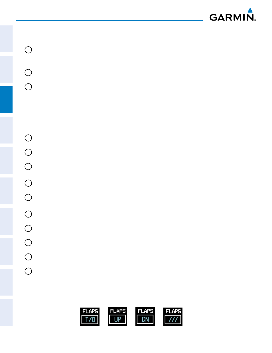
13
Trim/Flaps Group (ELEV
TRIM, RUDDER TRIM,
FLAPS)
Elevator and rudder trim are displayed on slide bars; the white portions
of the bars represent takeoff trim ranges
Flap position (UP, T/O, DN) is denoted; when the flaps are in transit
between positions, /// is displayed (Figure 3-2)
Flaps Up
Takeoff Flaps
Flaps Down
Flaps In Transit
Figure 3-2 Flap Positions