1 flight instruments, Airspeed indicator, Flight instruments – Garmin G1000 Mooney M20TN User Manual
Page 56
Garmin G1000 Pilot’s Guide for the Mooney M20M/M20R/M20TN
190-00647-02 Rev. A
42
FLIGHT INSTRUMENTS
SY
STEM
O
VER
VIEW
FLIGHT
INSTRUMENTS
EIS
AUDIO P
ANEL
& CNS
FLIGHT
MANA
GEMENT
HAZARD
AV
OID
ANCE
AFCS
ADDITIONAL FEA
TURES
APPENDICES
INDEX
2.1 FLIGHT INSTRUMENTS
AIRSPEED INDICATOR
NOTE:
Refer to the Aircraft Flight Manual (AFM) for airspeed criteria and Vspeed values.
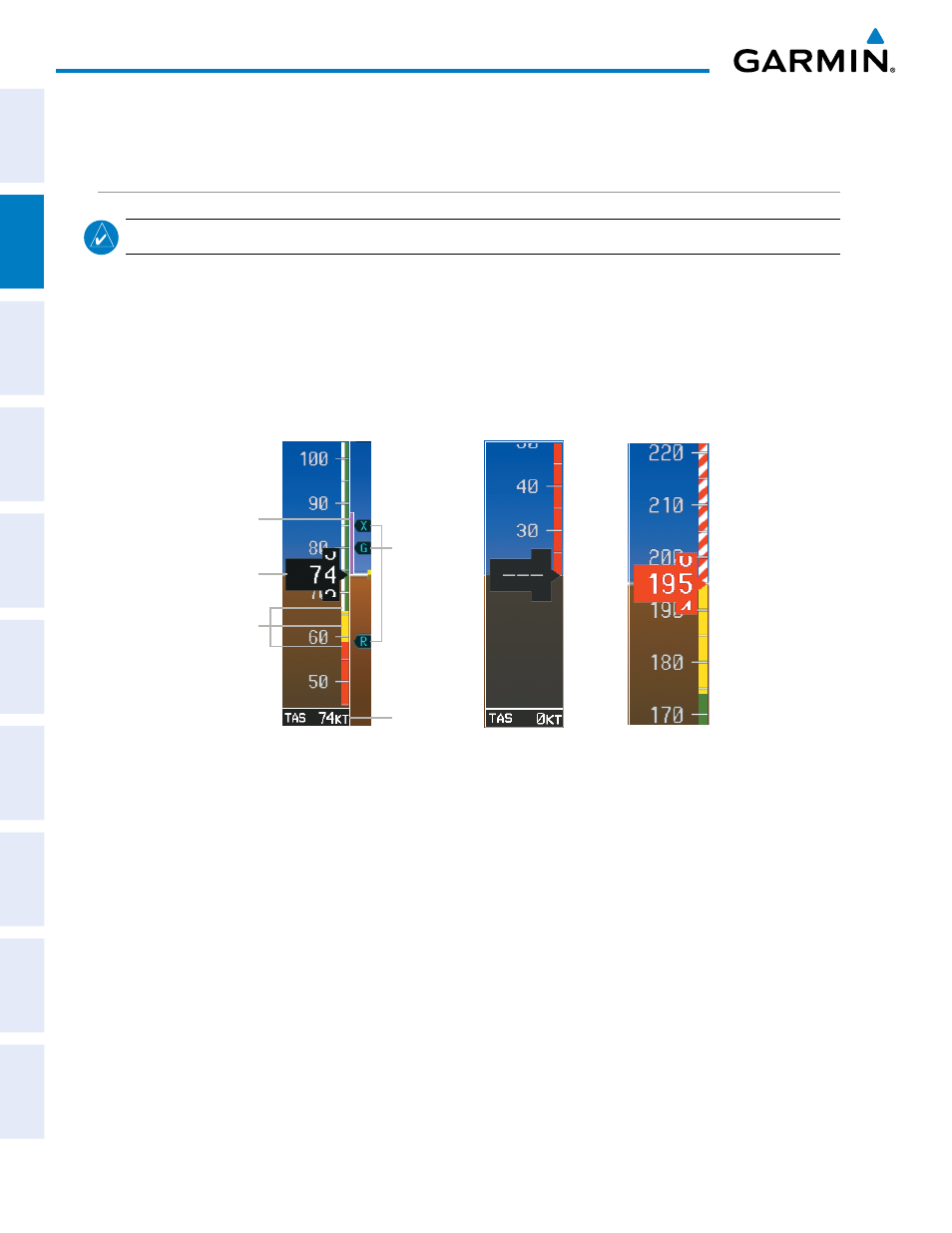
The Airspeed Indicator displays airspeed on a moving tape rolling number gauge. The true airspeed is
displayed in knots below the Airspeed Indicator. The numeric labels and major tick marks on the moving
tape are marked at intervals of 10 knots. The minor tick marks on the moving tape are marked at intervals of
five knots. Speed indication starts at 20 knots, with 60 knots of airspeed viewable at any time. The indicated
airspeed is displayed inside the black pointer. The pointer remains black until reaching maximum operating
speed (V
MO
), at which point it turns red.
Figure 2-3 Airspeed Indicator
Low Speed Range
Red Pointer at V
NE
Speed
Ranges
Indicated
Airspeed
Airspeed
Trend
Vector
True
Airspeed
Operating Ranges
Vspeed
References
Color coded stripes appear on the Airspeed Indicator to show the operating ranges. The low speed range
stripes are red and yellow. Normal operating range is green, caution range is yellow, and the never exceed speed
(V
NE
) begins with a red and white barber pole. The flap operating range is indicated by a white stripe.
The Airspeed Trend Vector is a vertical magenta line, extending up or down the airspeed scale to the right of
the speed range. The end of the trend vector indicates the predicted airspeed in six seconds if the current rate of
acceleration is maintained. If the trend vector crosses V
NE
, the number in the indicated airspeed pointer changes
to yellow. The trend vector is absent if the speed remains constant or if any data needed to calculate airspeed is
not available due to a system failure.