Icons, Laser classification, Electromagnetic compatibility (emc) – RIDGID micro DL-500 User Manual
Page 8: Changing/installing batteries
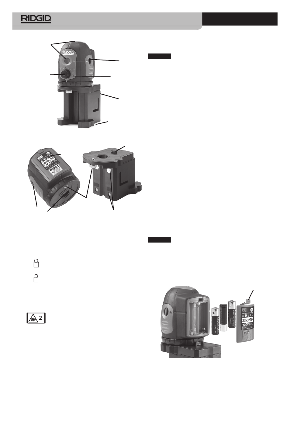
micro DL-500 Self-Leveling 5-Dot Laser
6
Laser
Windows
ON/OFF
Switch
Magnetic
Base
Figure 2 - Laser Parts
5
/
8
- 11 Thread
for Mounting
(Underside)
Laser
Window
Power Indicator
Light
Laser
Window
Battery
Door
Position
tab
Figure 3 - Laser Level Parts
1
/
4
- 20 Thread
for Mounting
Rare Earth
Magnets
Icons
LOCK
UNLOCK
Laser Classification
The RIDGID micro DL-500 Self- Leveling
5-Dot Laser generates visible laser
beams that are emitted from the top, bottom,
front and sides of the device.
The device complies with class 2 lasers accord-
ing to: EN 60825-1:1994/A11:1996/- A2:2001/
A1:2002
Electromagnetic
Compatibility (EMC)
The term electromagnetic compatibility is
taken to mean the capability of the prod-
uct to function smoothly in an environment
where electromagnetic radiation and elec-
trostatic discharges are present and without
causing electromagnet interference to other
equipment.
NOTICE
The RIDGID micro DL-500 Self-Leveling
5-Dot Laser conforms to all applicable EMC stan-
dards. However, the possibility of them causing
interference in other devices cannot be preclud-
ed.
Changing/Installing
Batteries
The RIDGID micro DL-500 Self-Leveling 5-Dot
Laser is supplied without batteries installed.
When the laser is ON, if the Power Indicator
Light blinks, the batteries need to be re-
placed. Remove the batteries prior to long
term storage to avoid battery leakage
1. Make sure the laser is OFF (ON/OFF
switch turned fully counter clockwise).
2. Remove the battery cover by depressing
the tab (Figure 4). If present, remove the
white sensormatic tag from the battery
compartment. Remove the batteries if
needed.
3. Install three AA (LR6) batteries into bat-
tery holder, observing the correct polar-
ity as indicated in the battery compart-
ment.
NOTICE
Use batteries that are of the same
type. Do not mix battery types. Do not mix
new and used batteries. Mixing batteries can
cause overheating and battery damage.
4. Securely replace the battery cover.
Tab
Figure 4 - Battery Installation