Level checks, Up beam check – RIDGID micro DL-500 User Manual
Page 10
micro DL-500 Self-Leveling 5-Dot Laser
8
3. Make sure the laser has been properly
inspected before each use.
4. Set up the micro DL-500 Laser for the ap-
plication. The laser unit can be mounted
directly to a tripod or other attachment
with the
5
/
8
" - 11 or
1
/
4
" - 20 thread. If us-
ing the base, align the tab on the base
mounting surface with the slot in the
bottom of the laser and secure with the
supplied
1
/
4
" - 20 screw.
The base can be placed on most rela-
tively flat, level surfaces. The base is also
equipped with magnets to allow mount
ing to steel objects in a variety of posi-
tions. Additionally, the base has top and
bottom sections that can be rotated rela-
tive to each other. See Figure 6 for com-
mon configuration.
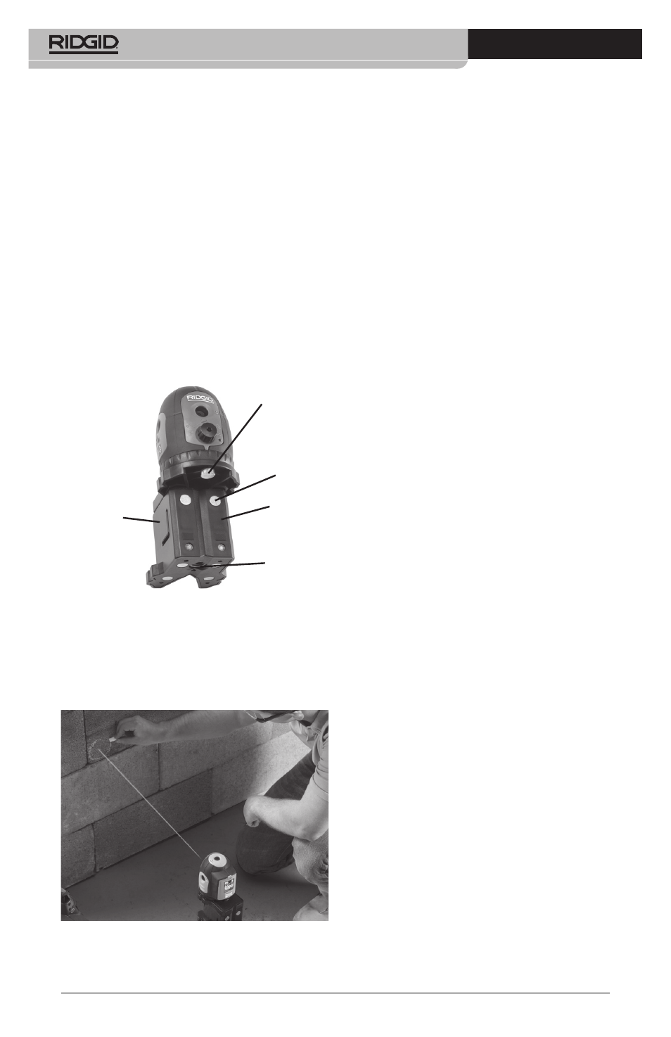
Strap Slots
1
/
4
" - 20
Screw
Magnets
Figure 6 -Base
5
/
8
" - 11
Thread
Base
In cases where the magnets will not
hold the laser in place (such as on plastic
pipe), use the mounting strap in the slots
on the base to retain the level in place.
Figure 7 - Using the mounting strap to hold
the Laser in position
Whatever configuration the laser is used
in, it must be secure and stable to pre-
vent the unit from tipping or falling. The
laser must be placed within +/-4.5 de-
grees of level to self level when turned
ON.
5. Keep your eyes and face clear of the la-
ser output windows. Turn the ON/OFF
switch fully clockwise. Five laser beams
will be generated (i.e. left, right, front,
up, and down) and will be visible as red
points on the adjacent surfaces. This will
also release the locking mechanism and
allow the laser unit to self-level. If the
laser is more than 4.5° from level, the
laser beam will flash and an intermittent
beep will sound. If this occurs, turn the
laser OFF and set up closer to level. De-
pending on the circumstances, the unit
should selflevel within a few seconds.
6. Once the laser is ON, the lasers can be
rotated to align with desired features. Do
not touch the laser unit while measure-
ments are being made – this can prevent
the laser from being level and give a false
reading. At this point, the laser beams
can be used as a reference point for mea-
surements, etc.
7. Any time the laser is not being used, turn
the laser OFF by turning the ON/OFF
switch counterclockwise to help prevent
inadvertent eye contact with the laser
beam.
8. While the laser is in the upright position,
lock the self-leveling mechanism prior to
transportation and storage by turning
the ON/OFF switch fully counterclock-
wise. Do not move the laser if the self-
leveling mechanism is not locked as this
can damage the unit.
Level Checks
Always check the Up Beam and the Horizontal
Beams prior to use to make sure that the unit
is properly leveling and calibrated.
Up Beam Check
1. With the laser attached to its base, set on
a flat surface inside a room. Turn the laser
ON.
2. Mark the location of the down beam on
the flat surface. This will be the reference
point.
3. Locate the up beam on the ceiling or sur-
face above the laser and mark its point
as position A. Measure the distance from