Functional circuit diagram, 24 mi ff – DE DIETRICH MS 24 User Manual
Page 92
92
71.03982.03 - EN
INSTALLATION INSTRUCTIONS
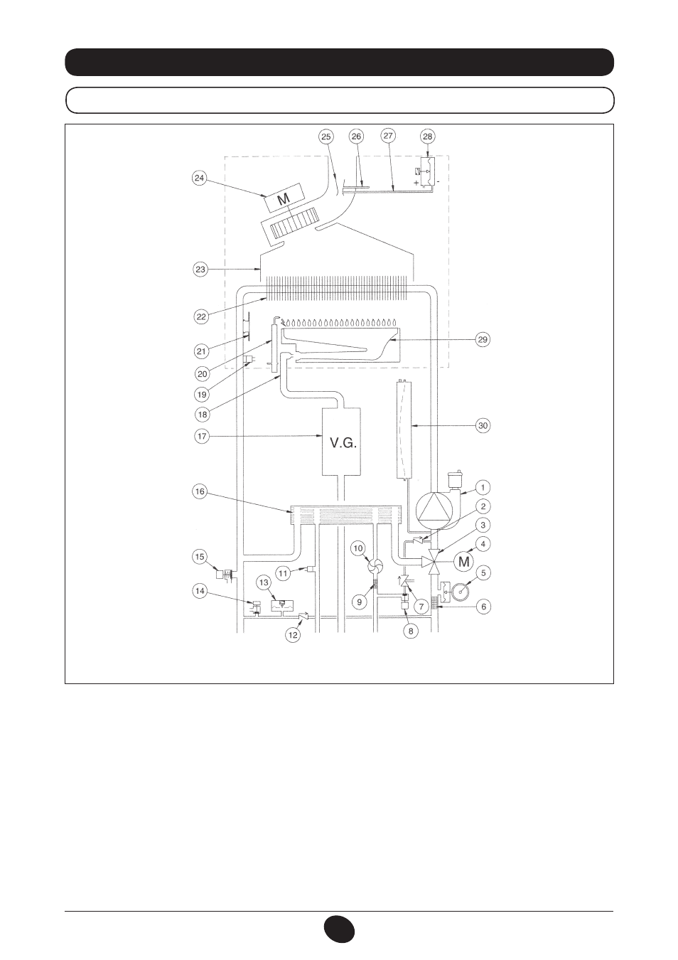
33. FUNCTIONAL CIRCUIT DIAGRAM
24 MI FF
Key:
1 Pump and air separator
2 No-return valve
3 Three-way valve
4 Three-way valve motor
5 Pressure gauge
6 Heating circuit extractable filter
7 Disconnector
8 Boiler filling tap
9 Cold water extractable filter
10 DHW priority sensor
11 NTC domestic hot water sensor
12 Check valve on automatic by-pass
13 Water pressure switch
14 Boiler drain tap
15 Safety valve
16 Water-water plate heat exchanger
17 Gas valve with gas diaphragm
18 Gas train with nozzles
19 Central heating NTC sensor
20 Ignition/flame detection electrode
21 Safety thermostat
22 Water-fumes exchanger
23 Fumes conveyor
24 Fan
25 Venturi tube
26 Positive pressure point
27 Negative pressure point
28 Air pressure switch
29 Burner
30 Expansion vessel
Figure 17
Heating flow
DHW
outlet
Gas
DHW
inlet
Heating return
CG_2269 / 1006_1805