Jumpers – Xilinx ML310 User Manual
Page 57
ML310 User Guide
57
UG068 (v1.01) August 25, 2004
1-800-255-7778
Board Hardware
R
Jumpers
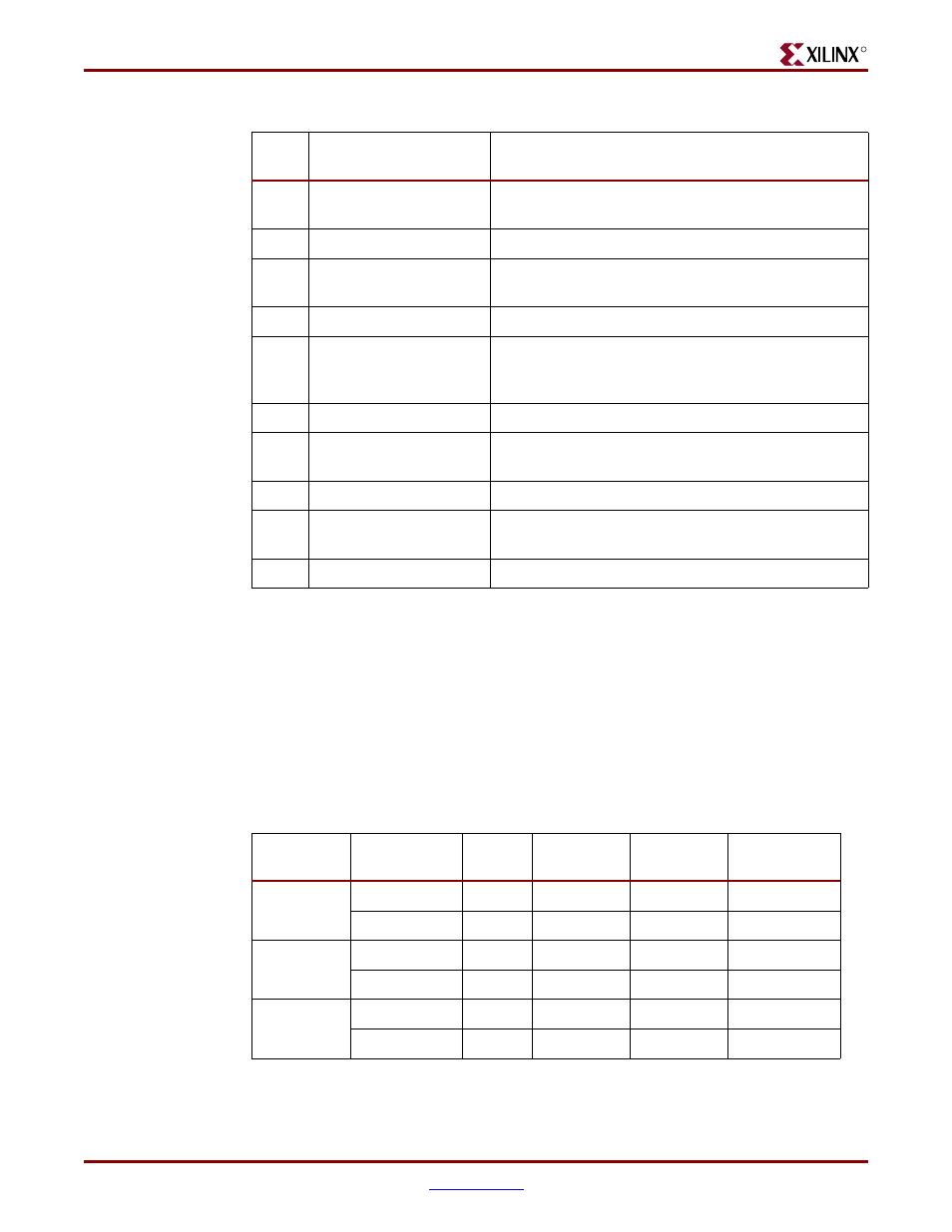
MGT VTRX Termination Voltage Jumpers, J10 and J11
The MGT receive termination voltage, VTRX, on the top and bottom MGTs are jumper
selectable via jumpers J10 (top) and J11 (bottom). The onboard regulated VTRX
termination voltage can be configured for AC or DC coupling, 1.8V or 2.5V respectively.
shows the MGT VTRX voltage selections available on the ML310 board.
15
KBINH
Tie this pin to GND to activate Keyboard inhibit, see
ALi M1536D+ data sheet for more details
16
VCC5V
5V ATX power available to user
17
ATX_IDELED_R
ATX IDE access indicator, Tie this pin to Anode of
user’s LED and Cathode to GND
18
VCC5V
5V ATX power available to user
19
PWR_SUPPLY_ON
Short this pin to GND to enable the ATX power
supply. Note: This pin cannot be controlled by a
momentary pulse.
20
GND
Ground
21
PB_SYSACE_RESET
Used to reset System ACE when driven low, as
described earlier,
22
GND
Ground
23
PB_FPGA_CPU_RESET
Used to reset CPU when driven low, as described
earlier,
24
GND
Ground
Table 2-25:
Front Panel Interface connector, J23
J23
Pin
Schem Signal
Description
Table 2-26:
Jumper Selection for Top and Bottom MGT VTRX Voltages,J10/J11
MGTs
VTRX
Voltage
Jumper
(J10)
Jumper
(J11)
MGT RX
Coupling
All Top
MGT_VTT
1.8V
Shunt 2 - 3
Open
AC
MGT_AVCC
2.5V
Shunt 1 - 2
Open
DC
All Bottom
MGT_VTT
1.8V
Open
Shunt 2 - 3
AC
MGT_AVCC
2.5V
Open
Shunt 1- 2
DC
All MGT_VTT
1.8V
Open
Open
Default
MGT_AVCC
2.5V
Open
Open
Default