Gpio, connector j5, System management bus (smbus) – Xilinx ML310 User Manual
Page 45
ML310 User Guide
45
UG068 (v1.01) August 25, 2004
1-800-255-7778
Board Hardware
R
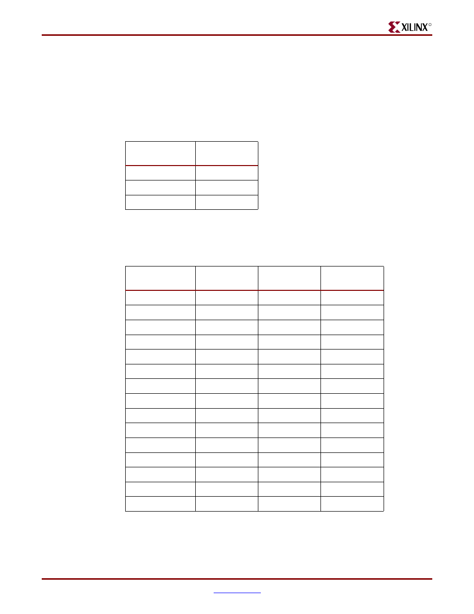
GPIO, connector J5
There are 15 GPIO pins connecting the ALi M1535D+ to the J5 24 pin header. These may be
accessed via the ALi M1535D+ via the PCI Bus. Please review the ALi M1535D+ Data
sheets for more detailed information.
shows the types and number of GPIO signals available to the user from the ALi
South Bridge.
shows the connections from the ALi, M1535D+, GPIO signals available at the
GPIO header (J5). Please review the ALi M1535D+ Data sheets, located on the ML310
CDROM, for more detailed information.
System Management Bus (SMBus)
The System Management Bus (SMBus) host controller in the M1535D+ supports the ability
to communicate with power related devices using the SMBus protocol. It provides quick
Table 2-17:
Type of GPIO Available on Header J5
ALi GPIO Types
Number
Available
Output
5
Input
4
Input/Output
6
Table 2-18:
GPIO Connections on Header J5
Schem Net Name
GPIO Header
(J5)
M1535D+
(U15)
IO Type
GPO_35
24
P19
Output
GPO_34
22
P18
Output
GPO_30
20
N18
Output
GPO_29
23
N17
Output
GPO_10
21
T3
Output
GPI_36
7
U8
Input
GPI_34
5
W7
Input
GPI_25
3
E9
Input
GPI_24
1
M17
Input
GPIO_3
15
Y4
Input/Output
GPIO_23
19
U5
Input/Output
GPIO_22
17
U6
Input/Output
GPIO_2
13
W4
Input/Output
GPIO_1
11
V4
Input/Output
GPIO_0
9
Y3
Input/Output