Front panel interface connector, j23 – Xilinx ML310 User Manual
Page 55
ML310 User Guide
55
UG068 (v1.01) August 25, 2004
1-800-255-7778
Board Hardware
R
SW3 = 0 0 0 (default)
Front Panel Interface Connector, J23
The Front panel Interface connector (J23) is a 24-pin header that accepts a standard IDC 24
pin connector (0.1inch pitch). J23 provides an optional means to control and gather status
information from the ML310 board if it were to be enclosed similar to that of a desktop PC.
The functionality listed below can easily be connected via a user build cable that connects
to some collection of user created logic the could be used to control/monitor the
functionality available via the Front Panel Interface.
The front panel interface provides the following control capability available through the
J23 header.
♦
Power on/off the ML310
-
ML310 board is delivered with a jumper installed on J23
♦
Select any of the eight System ACE configuration
-
Connects to the 3 System ACE configuration address lines
♦
System ACE Reset
-
Active low input
♦
CPU Reset
-
Active low input
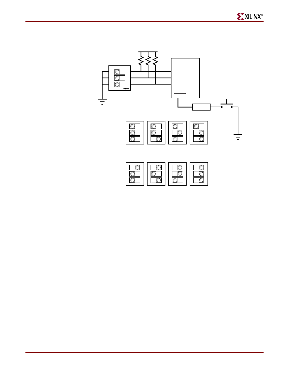
Figure 2-16:
SW3 - SysACE CFG Switch Detail
2.5V
ON
SW3
SYSACE CFG
3
2
1
2
1
0
CFGADDR
RESET
SYSACE_
RESET_N
Shown here with
CFGADDR[2:0]
set to "000".
ON => SW Closed
U38
SW1
System ACE
Debounce
U31
SYSACE
Reset
0x0
Default
0x1
0x2
0x3
0x4
0x5
0x6
0x7
CFGADDR[2:0] =